


Section 1
General Information
4-18 Programming & Operation MN722
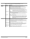
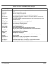
Table 4-5 Inverter Control Board Level 2 Parameter Definitions
Block Title Parameter Description
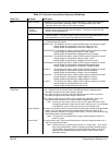
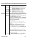
OUTPUT LIMITS Operating Zone Sets the PWM operating zone to Standard 2.5KHz or Quiet 8.0KHz output carrier
frequency. Two operating modes are also selectable: Constant Torque and Variable
Torque.
Constant Torque allows 170 - 200% for 3 seconds overload or 150% for 60 seconds
overload.
Variable Torque allows 115% peak overload for 60 seconds.
MIN Output Speed Sets the minimum motor speed in RPM. During operation, the motor speed will not be
allowed to go below this value except for motor starts from 0 RPM or during dynamic
braking to a stop.
MAX Output Speed Sets the maximum motor speed in RPM.
PK Current Limit The maximum output peak current to the motor. Values above 100% of the rated current
are available depending upon the operating zone selected.
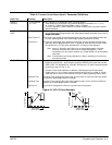
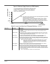
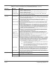
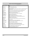
PWM Frequency The frequency that the output transistors are switched. PWM frequency is also referred
to as “Carrier” frequency. PWM should be as low as possible to minimize stress on
the output transistors and motor windings. It is recommended that the PWM
frequency be set to approximately 15 times the maximum output frequency of the
control. Ratios less than 15 will result in non-Sinusoidal current waveforms. See
Figure 4-3.
CUR Rate Limit Limits the rate of torque change in response to a torque command.
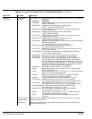
CUSTOM UNITS Decimal Places
Value At Speed
Units of Measure
The number of decimal places of the Output Rate display on the Keypad display. This
value will be automatically reduced for large values. The output rate display is only
available if the Value At Speed parameter value is non zero.
Sets the desired output rate per RPM of motor speed. Two numbers are displayed on
the keypad display (separated by a slash “/”). The first number (left most) is the value
you want the keypad to display at a specific motor speed. The second number (right
most) is the motor RPM corresponding to the units in the first number. A decimal may
be inserted into the left numbers by placing the flashing cursor over the up/down
arrow and use the arrow keys.
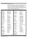
Allows user specified units of measure to be displayed on the Output Rate display. Use
the shift and arrow keys to scroll to the first and successive characters. If the
character you want is not displayed, move the flashing cursor over the special
up/down character arrow on the left side of the display. Use the up/down arrows and
the shift key to scroll through all 9 character sets. Use the ENTER key to save your
selection.
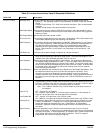
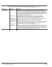
PROTECTION Overload Sets the protection mode to Fault (trip off during overload condition) or to Foldback
(automatically reduce the output current below the continuous output level) during an
overload. Foldback is the choice if continuous operation is desired. Fault will require
the control be “Reset” manually or automatically after an overload.
Note: The “Foldback” selection may not be available on some early versions of
the software.
External Trip OFF - External Trip is Disabled.
ON - External Trip is enabled. If a normally closed contact at J1-16 is opened, an
External Trip fault will occur and cause the drive to shut down.
Local Enable INP OFF - Ignores J1-8 input when in the “LOCAL” mode.
ON - Requires J1-8 input to be closed to enable the control when in the “LOCAL” mode.
Following Error This parameter determines if the control is to monitor the amount of following error that
occurs in an application. Following Error is the programmable tolerance for the AT
Speed Opto output as defined by the Level 1 Output block, AT Speed Band
parameter. Operation outside the speed range will cause a fault and the drive will
shut down.
Torque Proving When this parameter is set to ON the control measures output current in all three
phases to the motor. If output current is unbalanced, the control will trip off generating
a torque proving fault. In a hoist application, for example, this is useful to ensure that
motor torque exists before the fail safe brake is released. “Drive On” output, if
programmed, will not occur if torque proving fails.