


Section 1
General Information
Programming & Operation 4-11MN722
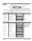
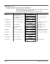
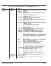
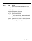
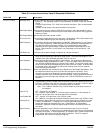
Table 4-2 Converter Control Board Parameter Definitions
Block Title Parameter Description
MISC Factory Settings Restores factory settings for converter section parameters. Select YES and press
ENTER to restore factory parameter values. The Keypad Display will show
“Operation Done” then return to “NO” when complete.
Line Inductor
(Boost
Regulator)
The value of the internal or external boost regulator inductor in “mH”. This parameter
sets the current loop gain of the converter section. This value is factory set and
should not require adjustment.
Bus Capacitance Sets the nominal DC Bus capacitance. This parameter sets the voltage loop gain for the
converter section. This value is factory set and should not require adjustment unless
more capacitance or more controls are added across the DC Bus.
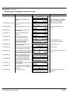
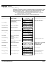
DAC Selection This parameter configures both Analog Outputs #1 (J1-6) and #2 (J1-7) at the same time
for troubleshooting purposes.
AB BC Cross- This selection provides a scaled 0-5VDC signals at Outputs #1 and #2.
Analog Output #1 represents the Line-Line voltage (L1–L2).
Analog Output #2 represents the Line-Line voltage (L2–L3).
DQ CONTRLR- This selection provides a scaled 0-5VDC signals at Outputs #1 and #2.
Analog Output #1 represents the Direct Control voltage.
Analog Output #2 represents the Quadrature Control voltage.
DQ Currents- This selection provides a scaled 0-5VDC signals at Outputs #1 and #2.
Analog Output #1 represents the Direct Control current.
Analog Output #2 represents the Quadrature Control current.
IQ Command-This selection provides a scaled 0-5VDC signals at Outputs #1 and #2.
Analog Output #1 represents the Quadrature Command signal.
Analog Output #2 represents the Quadrature Feedback signal.
IB and IC- This selection provides a scaled 0-5VDC signals at Outputs #1 and #2.
Analog Output #1 represents the Phase B current feedback.
Analog Output #2 represents the Phase C current feedback.
Va and Vb- This selection provides a scaled 0-5VDC signals at Outputs #1 and #2.
Analog Output #1 represents the PWM voltage for Phase A.
Analog Output #2 represents the PWM voltage for Phase B.
Ia and Ib- This selection provides a scaled 0-5VDC signals at Outputs #1 and #2.
Analog Output #1 represents Phase A current.
Analog Output #2 represents Phase B current.
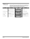
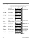
SECURITY
CONTROL
Security State Off - No security Access Code required to change parameter values.
Local - Requires security Access Code to be entered (using the keypad) before
parameter changes can be made using the Keypad.
Serial - Requires security Access Code to be entered (over the Serial Link) before
parameter changes can be made using the Serial Link.
Total - Requires security Access Code to be entered (using Keypad or Serial Link)
before parameter changes can be made using the Keypad or serial link.
Note: If security is set to Local, Serial or Total you can press PROG and scroll
through the parameter values and view their values but you are not allowed
to change their values unless you enter the correct access code.
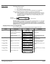
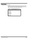
Access Timeout The time in seconds the security access remains enabled after leaving the programming
mode. If you exit and go back into the program Mode within this time limit, the
security Access Code does not have to be re-entered. This timer starts when leaving
the Program Mode (by pressing DISP).
Note: This feature is not available when using the Serial operating mode or if
power is cycled.
Access Code A 4 digit number code. Only persons that know the code can change secured Level 1
and Level 2 parameter values.
Note: Please record your access code and store it in a safe place. If you cannot
gain entry into parameter values to change a protected parameter, please
contact Baldor. Be prepared to give the 5 digit code shown on the lower
right side of the Keypad Display at the Security Control Access Code
parameter prompt.