


Section 1
General Information
4-14 Programming & Operation MN722
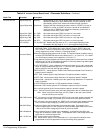
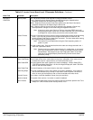
Table 4-4 Inverter Control Board Level 1 Parameter Definitions - Continued
Block Title Parameter Description
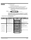
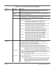
KEYPAD SETUP Keypad Stop Key
Keypad Stop Mode
Stop Key - Allows keypad “STOP” key to initiate motor stop during remote or serial
operation (if Stop key is set to Remote ON). If active, pressing “STOP”
automatically selects Local mode and initiates the stop command.
Stop Mode - Selects if the Stop command causes the motor to “COAST” to a stop or
“REGEN” to a stop. In COAST, the motor is turned off and allowed to
coast to a stop. In REGEN, the voltage and frequency to the motor is
reduced at a rate set by “Decel Time”.
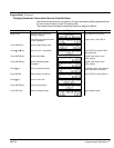
Keypad Run FWD
Keypad Run REV
Keypad Jog FWD
Keypad Jog REV
Loc. Hot Start
Run FWD - ON makes the keypad “FWD” key active in Local mode.
Run REV - ON makes the keypad “REV” key active in Local mode.
Jog FWD - ON makes the keypad “FWD” key active in Local Jog mode.
Jog REV - ON makes the keypad “REV” key active in Local Jog mode.
Loc. Hot Start OFF disables the Stop input at J1-11 in the keypad operating mode.
ON enables the Stop input at J1-11 in the keypad operating mode.
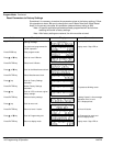
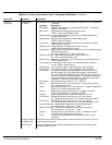
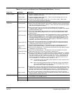
INPUT Operating Mode
Command Select
Ten “Operating Modes” are available. Choices are: Keypad, Standard Run, 15SPD, 3
SPD ANA 2 Wire, 3 SPD ANA 3 Wire, Serial, Bipolar, Process, EPOT 2 Wire and
EPOT 3 Wire. External connections to the control are made at the J1 terminal strip
(wiring diagrams are shown in Section 3 “Operating Modes”).
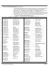
Selects the external speed reference to be used. The easiest method of speed control is
to select POTENTIOMETER and connect a 5KW pot to J1-1, J1-2, and J1-3. ±5, ±10VDC
or 4-20mA input command can be applied to J1-4 and J1-5.
If long distance is required between the external speed control and the control, the 4-20mA
selections at J1-4 and J1-5 should be considered. Current loop allows long cable lengths
without attenuation of the command signal.
10 VOLT W/TORQ FF - when a differential command is present at J1-4 and 5, allows addi-
tional 5V torque feedforward input at J1-1, 2 and 3 to set a predetermined amount of
torque inside the rate loop with high gain settings.
EXB PULSE FOL - selects optional Master Pulse Reference/Isolated Pulse Follower ex-
pansion board if installed.
5VOLT EXB - selects optional High Resolution I/O expansion board if installed.
10VOLT EXB - selects optional High Resolution I/O expansion board if installed.
4–20mA EXB – selects the 4–20mA input of the optional High Resolution I/O expansion
board if installed.
3-15 PSI EXB selects optional 3-15 PSI expansion board if installed.
Tachometer EXB- selects optional DC Tachometer expansion board if installed.
Serial -selects optional Serial Communications expansion board if installed.
None - Used in Process Control mode, two input configuration with no Feedforward input.
Note: When using the 4-20mA input, the JP1 jumper on the main control board
must be moved to pins 2 and 3.
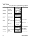
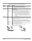
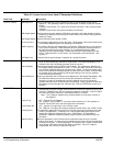
ANA CMD Inverse “OFF” will cause a low input voltage (e.g. 0VDC) to be a low motor speed command and
a maximum input voltage (e.g. 10VDC) to be a maximum motor speed command.
“ON” will cause a low input voltage (e.g. 0VDC) to be a maximum motor speed command
and a maximum input voltage (e.g. 10VDC) to be a low motor speed command.
ANA CMD Offset Provides an offset to the Analog Input to minimize signal drift. For example, if the
minimum speed signal is 1VDC (instead of 0VDC) the ANA CMD Offset can be set to
-10% so the minimum voltage input is seen by control as 0VDC.
ANA 2 Deadband
ANA 1 CUR Limit
Allows a defined range of voltage to be a deadband. A command signal within this
range will not affect the control output. The deadband value is the voltage above and
below the zero command signal level.
“OFF” Allows normal control operation.
“ON” Allows the 5V input at J1-2 (referenced to J1-1) to be used for reduction of the
programmed current limit parameter for torque trimming during operation.