


3-18 Receiving & Installation MN722
Control Board Jumpers
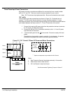
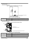
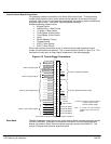
Converter Section Control Board
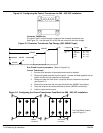
Figure 3-10 Converter Control Board Jumper JP1 Location
JP1
321
Keypad
Connector
Expansion Board Motor Control Board
See recommended terminal tightening
torques in Section 7.
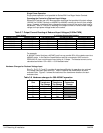
Table 3-9 Converter Control Board Jumper
Jumper Jumper Position Description of Jumper Position Setting
JP1
1–2 Voltage Speed Command Signal. (Factory Setting)
2–3 4–20mA Speed Command Signal.
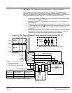
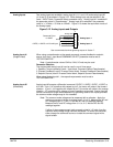
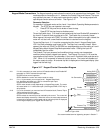
Inverter Section Control Board
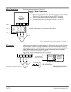
Figure 3-11 Inverter Control Board Jumper Locations
JP2
JP1
Refer to Table 3-10
for jumper placement information.
123
123
See recommended terminal tightening torques in Section 7.
Table 3-10 Inverter Control Board Jumper
Jumper Jumper Position Description of Jumper Position Setting
JP1
1-2 Voltage Speed Command Signal. (Factory Setting)
2-3 4-20mA input at Analog #2
JP2
1-2 Factory Setting
2-3 Not used.