


Section 1
General Information
3-20 Receiving & Installation MN722
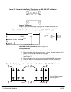
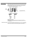
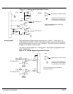
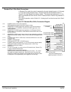
Figure 3-13 Analog Inputs Equivalent Circuits
500W
–
+
5.1V Zener
.033 mF
5KW
1.96KW
+15VDC
20KW
10KW 10KW
JP1
4-20mA
+
–
X N/C
To Microprocessor
10KW
10KW
To Microprocessor
Notes:
+
–
All OP Amps are TL082 or TL084
Analog Ground is separated from
Chassis Ground. Electrically they
are separated by an RC network.
30KW
-15VDC
J1
2
3
4
5
1
See recommended terminal tightening
torques in Section 7.
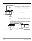
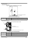
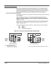
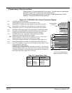
Analog Outputs Two programmable analog outputs are provided on J1-6 and J1-7. See Figure 3-14.
These outputs are scaled 0 - 5 VDC (1mA maximum output current) and can be used to
provide real-time status of various control conditions. The output conditions are defined
in Table 4-4 of Section 4 of this manual.
The return for these outputs is J1-1 analog ground. Each output is programmed in the
Level 1 Output block.
Figure 3-14 Analog Outputs Equivalent Circuits
+
–
10KW
10KW
.033 mf
50W
6
From Microprocessor
+
–
10KW
10KW
.033 mf
50W
7
From Microprocessor
Notes:
+
–
All OP Amps are TL082 or TL084
Analog Ground is separated from
Chassis Ground. Electrically they
are separated by an RC network.
1
J1
See recommended terminal tightening
torques in Section 7.