


Section 4
Programming and Operation
Programming & Operation 4-1MN722
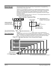
Overview The Series 22H Vector Line Regen Control has two control boards installed. The
“Converter Control Board” is used to rectify and process the incoming power. The
“Inverter Control Board” provides the inverting and power output functions. Each control
board has its own J1 terminal strip.
The Inverter Control Board normally has the keypad connected to it. The J1 terminal strip
of the Inverter Board provides the user interface for most external connections and
software parameters. The Inverter Control board is mounted above the Converter
Control Board.
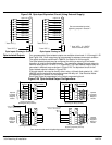
The Converter Control Board is programmed at the factory and should not require
program changes. However, you can change the values of several parameters within the
firmware (refer to parameters in Appendix B). The J1 terminal strip of the Converter
Control Board is factory wired for normal operation.
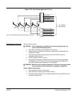
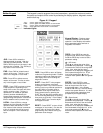
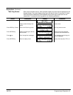
The keypad must be plugged into the Converter Control Board to change parameter
values, or access the fault log or the diagnostic information of the Converter Control
Board. A sheet metal panel separates the two control boards and there is a small access
hole the the sheet metal panel to attach the keypad to the Converter Control Board. To
attach the keypad to the Converter control board, use the following procedure:
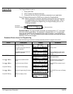
Keypad Installation in the Converter Control Board
1. Be sure all power is disconnected from the Series 22H Control. Wait at least 5
minutes for the bus capacitors to discharge before you proceed.
2. Open the Series 22H cover.
3. Remove the keypad from the Inverter Control Board (secured by 4 screws).
4. Remove the extension ribbon cable from its retaining strap (secured to the
sheet metal panel).
5. Connect one end of the ribbon cable into the keypad connector in the Converter
Control Board (through the access hole in the sheet metal panel).
6. Connect the other end of the ribbon cable to the keypad.
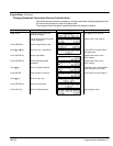
The control can now be powered up and the Converter Control Board can be
programmed or the fault log may be examined. To restore the keypad as factory
installed, use the following procedure:
Keypad Installation in the Inverter Control Board
1. Be sure all power is disconnected from the Series 22H Control. Wait at least 5
minutes for the bus capacitors to discharge before you proceed.
2. Remove the keypad from the ribbon cable and remove the ribbon cable from
the keypad connector in the Converter Control Board.
3. Store the extension ribbon cable in its retaining strap (secured to the sheet
metal panel).
4. Install the keypad on Inverter Control Board (secured by 4 screws).
5. Close and secure the Series 22H cover.