


Section 1
General Information
Receiving & Installation 3-33MN722
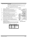
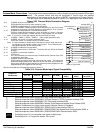
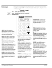
External Trip Input To activate the External Trip input, the External Trip parameter in the programming
Protection Block must be set to “ON”.
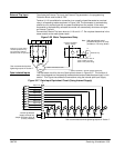
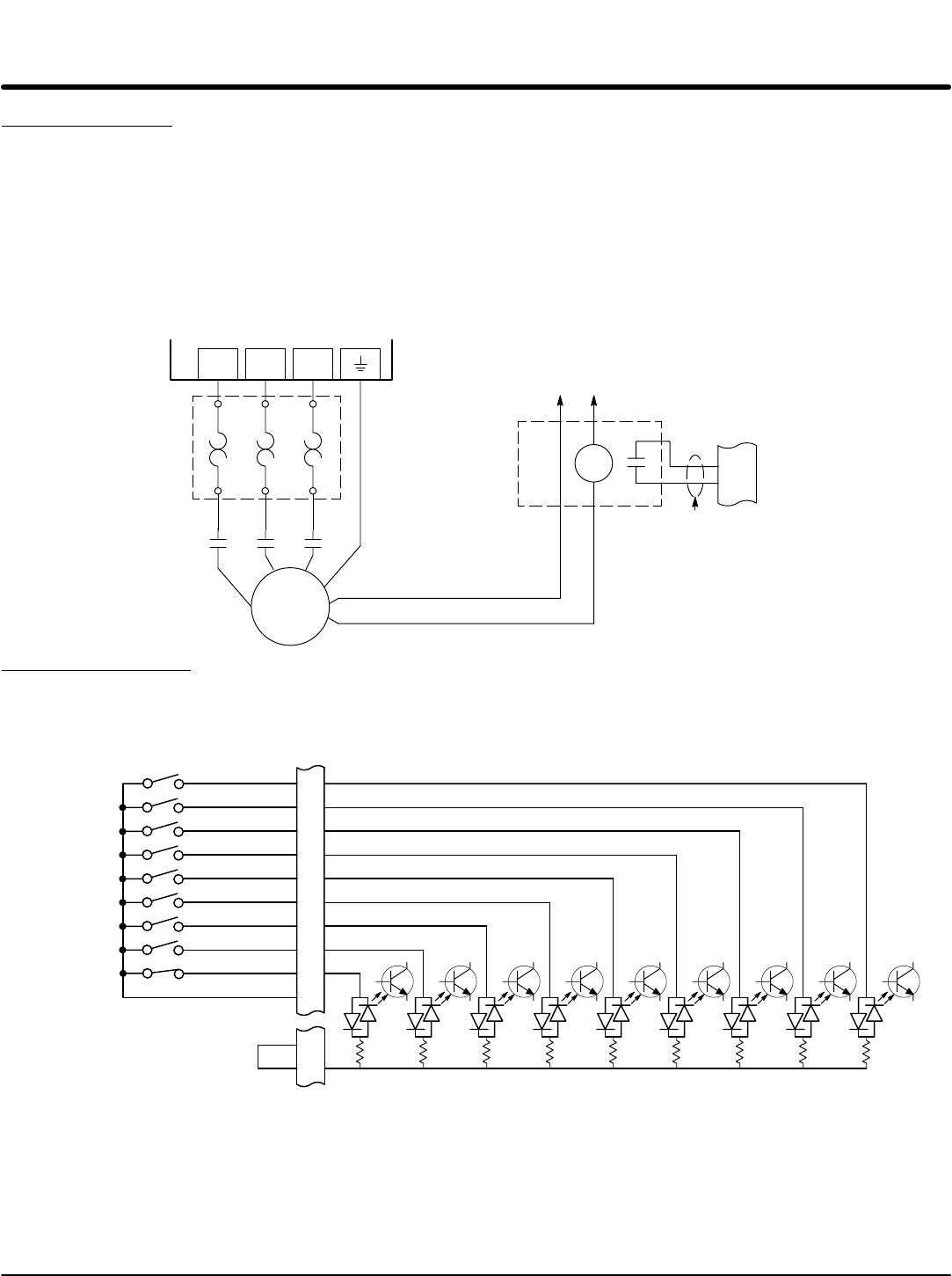
Terminal J1-16 is available for connection to a normally closed thermostat or overload
relay in all operating modes as shown in Figure 3-26. The thermostat or overload relay
should be a dry contact type with no power available from the contact. If the motor
thermostat or overload relay activates the control will automatically shut down and give
an External Trip fault.
Connect the External Trip Input wires to J1-16 and J1-17. Do not place these wires in the
same conduit as the motor power leads.
Figure 3-26 Motor Temperature Relay
T1 T2 T3
T1
T2
T3
G
* Motor
MMM
16
17
J1
External Trip
External or remote motor
overload protection may
be required by National
Electrical Code or equivalent
Do not run these wires in
same conduit as motor
leads or AC power wiring.
Customer Provided
Source Voltage
Motor Thermostat Leads
CR1
*
*
Optional hardware. Must be ordered separately.
Note: Add appropriately rated
protective device for AC relay
(snubber) or DC relay (diode).
See recommended terminal
tightening torques in Section 7.
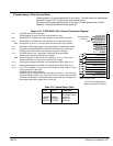
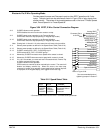
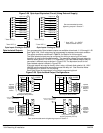
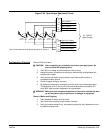
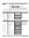
Opto-Isolated Inputs The equivalent circuit for the nine Opto inputs is shown in Figure 3-27. The function of
each input depends on the operating mode selected and are described previously in this
section. This Figure also shows the connections using the internal opto input Supply.
Figure 3-27 Opto-Input Equivalent Circuit (Using Internal Supply)
See recommended terminal tightening torques in Section 7.
+24VDC @ 200mA
(supply terminal 39).
Jumper terminals 39 to 40
(Factory Installed)
6.8K 6.8K 6.8K 6.8K 6.8K 6.8K 6.8K 6.8K 6.8K
15
16
17
39
40
Opto In #8
Opto In #9
Opto In Common
8
9
10
11
12
13
14
J1
Opto In #1
Opto In #2
Opto In #3
Opto In #4
Opto In #5
Opto In #6
Opto In #7