


Section 1
General Information
3-30 Receiving & Installation MN722
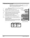
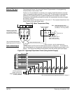
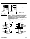
Process Mode Connections The process control mode provides an auxiliary closed loop general purpose PID set point
control. The process control loop may be configured in various ways and detailed
descriptions of the process mode are given in MN707 “Introduction to Process Control”.
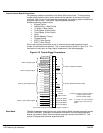
The opto inputs can be switches as shown in Figure 3-23 or logic signals from another device.
Figure 3-23 Process Mode Connection Diagram
See recommended terminal tightening torques in Section 7.
8
9
10
11
12
13
14
15
16
17
Enable
Forward Enable
Reverse Enable
Table Select
Speed/Torque
Process Mode Enable
External Trip
Opto In Common
Analog GND
Analog Input 1
Pot Reference
Analog Input +2
Analog Input -2
Analog Out 1
Analog Out 2
1
2
3
4
5
6
7
Jog
Fault Reset
J1
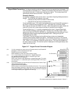
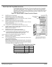
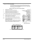
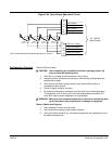
Refer to Figure 3-26.
J1-8 CLOSED allows normal operation.
OPEN disables the control & motor coasts to a stop.
J1-9 CLOSED to enable operation in the Forward direction.
OPEN TO DISABLE Forward operation (drive will brake to a stop if a Forward
command is still present). Reverse operation is still possible if J1-10 is closed.
J1-10 CLOSED to enable operation in the Reverse direction.
OPEN to disable Reverse operation (drive will brake to a stop if a Reverse
command is still present). Forward operation is still possible if J1-9 is closed.
Note: If J1-9 and J1-10 are both opened, the drive will brake to a stop.
J1-11 CLOSED = TABLE 1, OPEN = TABLE 0. (See multiple parameter sets.)
J1-12 CLOSED, the control is in torque command mode.
OPEN, the control is in speed (velocity) command mode.
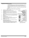
Note: If a stop command is issued while in the torque (current) mode, the control
will stop but will not maintain position (zero current). This is different than
zero speed operation for the velocity mode.
J1-13 CLOSED to enable the Process Mode.
J1-14 CLOSED places control in JOG mode. The control will only JOG in the forward
direction.
J1-15 CLOSED to reset a fault condition.
OPEN to run.
J1-16 If J1-16 is connected, you must set Level 2 Protection block, External Trip to “ON”
to activate the opto input.
CLOSED allows normal operation.
OPEN causes an external trip to be received by the control. The control will
disable and display external trip. When this occurs, the motor stop command is
issued, drive operation is terminated and an external trip fault is displayed on the
keypad display (also logged into the fault log).
5KW
Command Pot or
0-10VDC
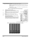
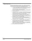
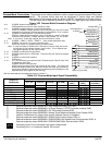
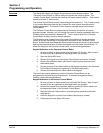
Table 3-15 Process Mode Input Signal Compatibility
Feedback
Setpoint or
Feedforward
J1-1 & 2 J1-4 & 5
5V EXB 10V EXB
4-20mA
EXB
3-15 PSI
EXB
DC
Tach EXB
J1-1 & 2
J1-4 & 5
5V EXB
10V EXB
4-20mA EXB
3-15 PSI EXB
DC Tach EXB
EXB PULSE FOL
Serial EXB
Requires expansion board EXB007A01 (High Resolution Analog I/O EXB).
Requires expansion board EXB004A01 (4 Output Relays/3-15 PSI Pneumatic Interface EXB).
Requires expansion board EXB006A01 (DC Tachometer Interface EXB).
Requires expansion board EXB005A01 (Master Pulse Reference/Isolated Pulse Follower EXB).
Used for Feedforward only. Must not be used for Setpoint Source or Feedback.
Requires expansion board EXB001A01 (RS232 Serial Communication EXB). or
Requires expansion board EXB002A01 (RS422/RS485 High Speed Serial Communication EXB). or
Requires expansion board EXB012A01 (RS232/RS485 Serial Communication EXB).
Conflicting inputs. Do not use same input signal multiple times.
Conflicting level 1 or 2 expansion boards. Do not use!