


Section 1
General Information
Receiving & Installation 3-27MN722
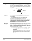
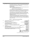
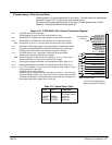
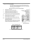
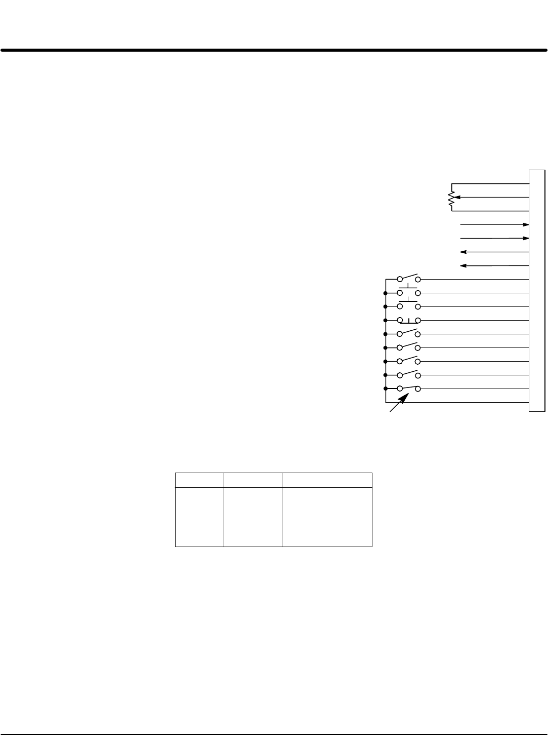
3 Speed Analog 3 Wire Operating Mode
Allows selection of 3 preset speeds with 3 wire inputs. The opto inputs can be switches
as shown in Figure 3-21 or logic signals from another device.
The values of the preset speeds are set in the Level 1 Preset Speeds block, Preset
Speed #1, Preset Speed #2 and Preset Speed #3.
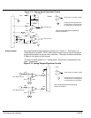
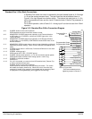
Figure 3-21 3 SPD ANA 3 Wire Control Connection Diagram
See recommended terminal
tightening torques in Section 7.
8
9
10
11
12
13
14
15
16
17
Enable
Forward Run
Reverse Run
Stop
Run Command
Speed Command
External Trip
Opto In Common
Analog GND
Analog Input 1
Pot Reference
Analog Input +2
Analog Input -2
Analog Out 1
Analog Out 2
1
2
3
4
5
6
7
Switch 1
Switch 2
J1
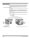
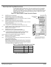
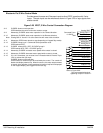
Refer to Figure 3-26.
J1-8 CLOSED allows normal operation.
OPEN disables the control and the motor coasts to a stop.
J1-9 MOMENTARY CLOSED starts motor operation in the Forward direction.
J1-10 MOMENTARY CLOSED starts motor operation in the Reverse direction.
Note: Closing both J1-9 and J1-10 at the same time will reset a fault condition.
J1-11 Momentary OPEN motor decels to stop (depending on Keypad Stop mode).
J1-12 CLOSED selects STOP/START and Reset commands from terminal strip.
OPEN selects STOP/START and Reset commands from Keypad.
J1-13 CLOSED selects Level 1 Input block, Command Select parameter.
OPEN selects speed commanded from Keypad.
Note: When changing from Terminal Strip to Keypad (J1-12 or J1-13) the motor
speed and direction will remain the same after the change.
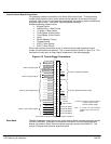
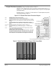
J1-14 Selects preset speeds as defined in the Speed Select Table (Table 3-13).
J1-15 Selects preset speeds as defined in the Speed Select Table (Table 3-13).
J1-16 If J1-16 is connected, you must set Level 2 Protection block, External Trip to
“ON” to activate the opto input.
CLOSED allows normal operation.
OPEN causes an external trip to be received by the control. The control will
disable and display external trip. When this occurs, the motor stop command
is issued, drive operation is terminated and an external trip fault is displayed on
the keypad display (also logged into the fault log).
5KW
Command Pot or
0-10VDC
Table 3-13 Speed Select Table
J1-14 J1-15 Command
Analog Input
(Command Select)
Preset #1
Preset #2
Preset #3
OPEN
OPEN
CLOSED
CLOSED
OPEN
CLOSED
OPEN
CLOSED