


PERF SONG PATTERN MIX MASTER REMOTE UTILITY
QUICK SET
FILEVOICE
MOXF6/MOXF8 Reference Manual
Voice Mode
Voice Play
[F1] PLAY
[F3] PORTA
[F4] EG
[F5] ARP ED
[F6] EFFECT
Arpeggio Edit
[F2] TYPE
[F3] MAIN
[F4] LIMIT
[F5] PLAY FX
Normal Voice Edit
Common Edit
[F1] GENERAL
[F2] OUTPUT
[F3] EQ
[F4] CTL SET
[F5] LFO
[F6] EFFECT
Element Edit
[F1] OSC
[F2] PITCH
[F3] FILTER
[F4] AMP
[F5] LFO
[F6] EQ
Drum Voice Edit
Common Edit
[F1] GENERAL
[F2] OUTPUT
[F3] EQ
[F4] CTL SET
[F6] EFFECT
Key Edit
[F1] OSC
[F2] PITCH
[F3] FILTER
[F4] AMP
[F6] EQ
Voice Job
[F1] INIT
[F2] RECALL
[F3] COPY
[F4] BULK
Supplementary Information
34
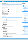
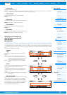
[SF3] PHASE
Phase
Determines the starting phase point for the LFO Wave when it is reset.
Settings: 0, 90, 120, 180, 240, 270
OFFSET EL1 – EL8
Determines the offset values of the “Phase” parameter (above) for the respective Elements.
Settings: +0, +90, +120, +180, +240, +270
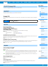
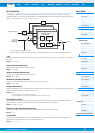
[SF4] BOX
From this display you can select the destination parameter for the LFO (in other words, which aspect of the sound the
LFO controls), the Elements to be affected by the LFO, and the LFO Depth. The available three pages (boxes) for
setting the destination let you assign multiple destinations.
ElmSw (LFO Element Switch)
Determines whether or not each Element is to be affected by the LFO.
Dest (Control Destination)
Determines the functions which will be controlled by the LFO Wave.
Settings: See the “Control List” in the “Data List” PDF document.
NOTE Regarding “Insertion Effect A Parameter 1 - 16,” “Insertion Effect B Parameter 1 - 16” and “Insertion Effect L Parameter 1 - 32”
described in the Control List, the actual parameter names of the selected Effect type are shown on the display. If one of these
names is shown, no function is assigned to that parameter.
Depth
Set the LFO Wave Depth (amplitude).
Settings: 0 – 127
DPTRATIO (Depth Ratio) EL1 – EL8
Determines the offset values of the “Depth” parameter (above) for the respective Elements.
Settings: 0 – 127
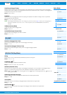
[SF5] USER
This menu is available only when the “Wave” parameter is set to “user.” You can create a custom LFO wave consisting of
up to sixteen steps.
Template
This includes pre-programmed settings for creating an original LFO. You can set the wave randomly by pressing the
[SF1] RANDOM button.
Settings: all-64.................. Values of all steps are set to -64.
all0.....................Values of all steps are set to 0.
all+64................. Values of all steps are set to +63.
sawup................ Creates a saw shaped upward wave.
sawdown ...........Creates a saw shaped downward wave
evnstep..............Values of all even steps are set to -64, and values of all odd steps are set to +63.
oddstep.............Values of all odd steps are set to -64, and values of all even steps are set to +63.
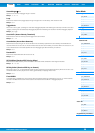
Slope
Determines the slope or ramp characteristics of the LFO wave.
Settings: off (no slope), up, down, up&down
Value (Step Value)
Determines the level for each step set in the “Step” parameter.
Settings: -64 – +0 – +63
Step
Numerator: Selects the desired step.
Settings: 1 – 16
Denominator: Determines the maximum number of steps.
Settings: 2, 3, 4, 6, 8, 12, 16