


Using a Quantum 984 HSBY System
840 USE 106 00 January 2003 83
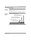
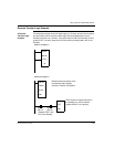
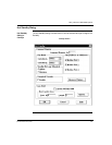
Reverse Transfer Logic Example
A Reverse
Transfer Logic
Example
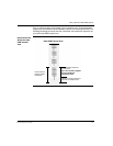
The following example shows I/O ladder logic for a Primary controller that monitors
two fault lamps and the reverse transfer logic that sends status data from the
Standby controller to the Primary. One fault lamp turns ON if the Standby memory
protect is OFF; the other lamp turns ON if the memory backup battery fails in the
Standby.
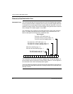
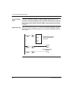
400005
400100
CHS
30
Network 1 of Segment 1
Network 2 of Segment 1
400103
000801
#001
BLKM
400101
STAT
#001
BLKM transfers the status of the
Hot Standby status register
(40103) to internal coils (00801)
000815
(Bit 15)
000816
(Bit 16)
STAT sends one register Word from
the standby to a reverse transfer
register (400101 in the primary.
(Enables STAT if this
PLC is the Standby