


Ethernet Hot Standby Solution
166
840 USE 106 00 January 2003
Hot Standby Topology
Hot Standby
Interconnection
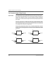
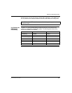
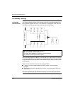
The following diagram shows a Hot Standby system the relationship between the
two redundant systems.Two CHS 110 modules are connected via a fiber optic link.
The RIOs are connected both to each other and to the RIO Drops.
In the preceding diagram the NOEs are connected to the same switch. Connecting
to the same switch is recommended but not required. Connecting to the same switch
is recommended because the NOEs communicate with each other in order to swap
the IP address.
There are two reasons for connecting to the same switch:
If a failure to communicate between the NOEs occurs, the time to swap
increases.
Therefore to minimize the probability of a failure, connect the two NOEs to the
same switch.
The other requirement for the switches is that they are on the same sub network.
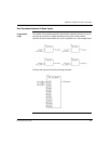
Note: The following three items are important.
1. The two systems must be identical.
2. The order of the modules in each rack must be the same.
3. The software revisions must be the same.
Ethernet Switch
Fiber Optic
Cable
T Connector
Drop
Drop
N
O
E
C
P
U
C
H
S
R
I
O
N
O
E
C
P
U
C
H
S
R
I
O