


Using a Quantum 984 HSBY System
78
840 USE 106 00 January 2003
Elements of the Nontransfer Area
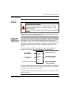
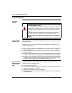
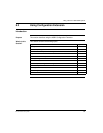
Nontransfer Area The most important part of the nontransfer area is the Hot Standby status register.
Once the system has been configured and is running, the status register becomes
a valuable tool for monitoring the machine states of the two controllers. If you use
software to change values in the command register, being able to see the result of
those changes in the status register is very helpful.
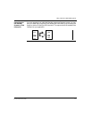
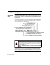
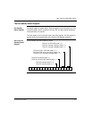
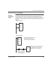
The nontransfer area is defined in the middle and bottom nodes of the instruction
block. The middle node specifies the first register in the nontransfer area. The
bottom node specifies the length of the nontransfer area.
The nontransfer area must be at least four registers long. The first two registers in
the nontransfer area are reserved for reverse transfer functions. The third register in
the nontransfer area is the Hot Standby status register.
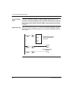
The fourth register and all other contiguous 4x registers specified for nontransfer are
ignored when the state RAM values of the Primary controller are transferred to the
Standby controller.
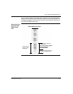
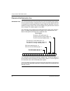
This PLC in OFFLINE mode = 0 1
This PLC running in primary mode =1 0
This PLC running in standby mode = 1 1
The other PLC in OFFLINE mode = 0 1
The other PLC running in primary mode =1 0
The other PLC running in standby mode = 1 1
PLCs have matching logic = 0
PLCs do not have matching logic = 1
This PLC’s switch set to A = 0
This PLC’s switch set to B = 1
1 2 34 56 7 8 9 10111213141516
Status Register