


Using a Quantum IEC Hot Standby System
840 USE 106 00 January 2003 139
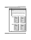
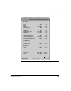
Start Standby The following table shows the steps to starting Standby.
Step Action
1 Start the Standby controller.
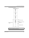
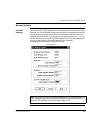
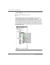
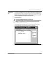
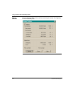
2 Check the LED display. If the system is functioning normally, the display should
be as follows:
On the CHS 110 module, all three indicators should be steady, not blinking.
A blinking Com Act light signals that your system has detected an error.
On the corresponding CRP module, the Ready indicator is a steady green.
The Com Act indicator on the Primary unit should also be a steady green,
while the Com Act indicator on the Standby RIO head should be blinking
slowly
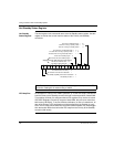
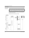
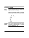
Illustrations of the Primary and Standby Backplanes are shown below.
Active
Ready Fault
Run Bal Low
Pwr ok
Modbus Com Err
Modbus! Error A
Com Act Error B
Primary
Mem Prt Standby
Active
Ready Fault
Run Bal Low
Pwr ok
Modbus Com Err
Modbus! Error A
Com Act Error B
Primary
Mem Prt Standby
Active
Ready Fault
Run Bal Low
Pwr ok
Modbus Com Err
Modbus! Error A
Com Act Error B
Primary
Mem Prt Standby
Active
Ready Fault
Run Bal Low
Pwr ok
Modbus Com Err
Modbus! Error A
Com Act Error B
Primary
Mem Prt Standby
140
CHS 110 00
HOT STANDBY
CHS 110 00
HOT STANDBY
RIO Head
HOT STANDBY
RIO Head
HOT STANDBY
140
Primary
Backplane
Standby
Backplane