


Planning a Quantum Hot Standby System
56
840 USE 106 00 January 2003
Guidelines for Planning a Hot Standby System
Primary and
Standby
Controllers
Both the primary and the standby controller in your Hot Standby system must be
ready to perform as a stand-alone controller in the event that its counterpart fails.
Therefore, you should install them with equal care, according to Modicon’s standard
planning and installation guidelines. Refer to the
Quantum Automation Series
Hardware Reference Guide,
840 USE 100 00, and the
Remote I/O Cable System
Planning and Installation Guide,
890 USE 101 00, for details.
Design your system for safety first, then for economy. Be sure that you understand
all the cautions and warnings in this manual before you begin to install your system.
For the Hot Standby system to function, your component modules must meet the
version requirements in
Overview of Quantum Hot Standby, p. 13
.
You must use identical modules in the primary and standby racks. If you have
different models or different versions of the same model or different flash executive
software, the Hot Standby system will not function properly.
While the controllers and RIO heads must be Quantum models, the remote drops
may use Quantum, 800 series, 500 series or 200 series I/O with corresponding drop
processors.
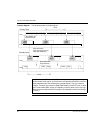
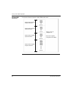
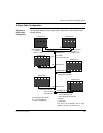
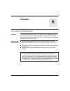
Positioning The CHS 110 Hot Standby modules are connected by fiber optic cable. A 3 meter
cable is supplied with the kit. However, the primary and standby backplanes may be
placed as much as 1 km apart. If you will be placing the modules more than 3 m
apart, use 62.5/125 micrometer cable with ST-style connectors. Refer to
Fiber Optic
Cable Guide, p. 213
for details.
If you intend to place the units more than 3 meters apart, you must consider the
effect on the RIO network and any Modbus Plus network.
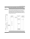
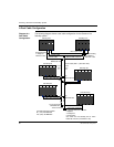
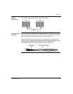
The controllers are linked to the RIO network by coaxial cable. The longer the
distance between the controllers, the higher the grade of trunk cable required to
maintain signal integrity. Refer to Chapter 3 of the
Remote I/O Cable System
Planning and Installation Guide
, 890 USE 101 00, for details regarding cable grades,
distances and signal integrity. If no coaxial cable will be sufficient to maintain signal
integrity throughout the RIO network, fiber optic repeaters may be used to boost the
signal. Refer to the
Modbus Plus Network Planning and Installation Guide,
890 USE
100 00,
for details on extending a Modbus Plus network.
Note: The order of the modules in the backplanes must be the same.