


Theory of 984 HSBY Operation
34
840 USE 106 00 January 2003
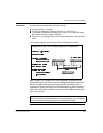
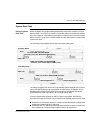
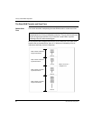
The normal Hot Standby configuration contains:
In the local rack: power supply (CPS), PLC (CPU), RIO Head (CRP 93x), Hot
Standby module (CHS)
In one remote IO drop equipped with 8 I/O modules, power supply (CPS) and
remote adapter (CRA)
Only the logic for the scan time evaluation
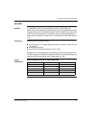
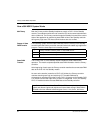
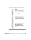
PLC Scan Times The scan time increase with different PLCs, after adding HSBY, is outlined in the
Scan Time Increase table below.
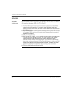
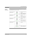
PLC to CHS Data
Transfer Rate
The investigation of the PLC specific data transfer rate in a Hot Standby system
leads to the following results.
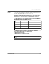
State RAM The following table lists the number of bytes required for reference storage in state
RAM.
Based on the data shown in the tables above you may forecast the overall scan time
of a Hot Standby system once you know how much state RAM is going to be
transferred and the time required for a particular logic application to be executed in
a standalone system.
CPU - HSBY Baseline
Configuration
Scantime Increase
because of HSBY
Languages Supported
CPU x13 0x0x: 1536, 1x: 512, 3x:
3000, 4x: 1872
~ 25 ms 984 Ladder Logic only
CPU 424 020x: 1536, 1x: 512, 3x:
1212, 4x: 1872
~ 40 ms 984 Ladder Logic only
CPU 434 12 / CPU 534 140x:
1536, 1x: 512, 3x: 512, 4x: 1872
~ 40 ms 984 Ladder Logic only
CPU x13 0x 1.6 ms / byte
CPU 424 02 2.0 ms / byte
CPU 434 12 /
CPU 534 14
1.9 ms / byte
Coil (0x) 3 bit
Discrete (1x) 3 bit
Input Register (3x) 2 bytes
Holding Register (4x) 2 bytes plus 2 bit