


Using a Quantum IEC Hot Standby System
840 USE 106 00 January 2003 131
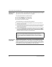
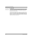
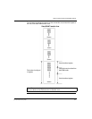
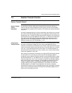
The following block diagram shows how the nontransfer area exists with respect to
the rest of the state RAM transfer area.
Note: The command register must not be placed in the nontransfer area. No more
than one block can be defined as the nontransfer area.
0nnnnn
1nnnnn
3nnnnn
4nnnnn
Total number of configured
4x registers
Actual transferred registers
Nontransfer area is excluded from
state RAM transfer
Actual transferred registers
State RAM Transfer Area