


Using a Quantum 984 HSBY System
840 USE 106 00 January 2003 73
CHS Instruction
Using CHS
Instruction
Segment 1 may contain the ladder logic for diagnostics and optional Hot Standby
functions, such as time-of-day clock updates.
Using the CHS
Instruction to
Control Your Hot
Standby System
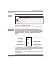
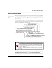
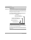
If you choose to use the CHS instruction in ladder logic to control the Hot Standby
configuration, the instruction must be placed in network 1, segment 1 of the ladder
logic program. The top node must be connected directly to the power rail by a
horizontal short. No control logic, such as contacts, should be placed between the
rail and the input to the top node. However, other logic may be placed in network 1.
Remember, the ladder logic in the Primary and Standby controllers must be
identical.
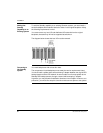
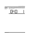
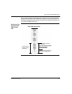
The three nodes in the CHS instruction define the command register, the first
register in the nontransfer area, and the length of the nontransfer area.
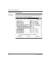
The bottom output node of the CHS instruction indicates whether the configuration
extension screens have been activated and allows the parameters in the screens to
override those in the CHS instruction at startup.
A detailed description of the CHS instruction is provided in the
Ladder Logic Block
Library User Guide
.
CAUTION
Reschedule Segment Hazard
To help protect against damage to application I/O devices through
unexpected system actions, do not reschedule segment 1 via the
segment scheduler.
Failure to follow this precaution can result in injury or equipment
damage.
nontransfer
area
length
CHS
command
register
Execute HSBY
Unconditionally
Enable
Command
Registe
r
Enable
Nontransfer Area
HSBY System ACTIVE
PLC cannot communicate
with its CHS module
Configuration extension
screens are defining the
HSBY configuration