


Installation
840 USE 106 00 January 2003 65
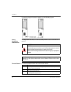
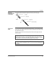
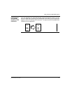
Diagram of
Aligning Key and
Locking Ring
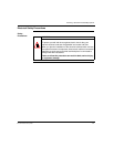
The diagram below illustrates the alignment of the key and locking ring.
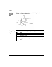
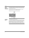
Attaching the
Cable
Turn the cable to the right, so that the tab locks securely. You may leave the fiber
cable clasp on the cable for future use, but slide it off the boot of the cable to allow
the module door to close.
Repeat this process with the remaining strand of cable and the upper (transmit)
cable connector.
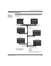
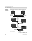
Note: Remember that each strand of cable must be connected to the upper
(transmit) cable connector on one Hot Standby module and the lower (receive)
cable connector on the other. If the cable is not properly connected, the modules
will not be able to communicate and the Standby will remain offline.
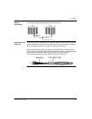
Note: One strand of the cable provided in the CHS 210 Hot Standby kit is marked—
for instance, with the manufacturer's name. This is the only way to distinguish the
two strands.