


Theory of IEC HSBY Operation
840 USE 106 00 January 2003 53
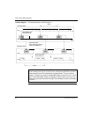
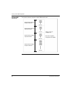
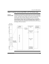
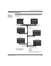
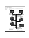
Layout of completely transferred state RAM in an IEC Hot Standby system
Layout of
transferred RAM
The diagram below illustrates that a significant piece of the controller’s state RAM is
taken as a transfer buffer for copying the IEC heap from the Primary to the Standby
controller. The transfer header is located at the very top of the transfer buffer. The
transfer header contains information about the Primary’s exec version, time
synchronization information and the IEC application’s version. This information
allows the Standby controller, once it received the transfer buffer, to decide whether
to remain online or go offline. When online, the Standby controller copies the
Primary’s IEC heap out of the transfer buffer into its internal memory, which ensures
the Standby’s IEC data consistency.
Header
(Exec Vers.,
Timing Info, ..,)
Program Data
Used
Safety Buffer
for Future
changes/additions
Program Data
Unused
Prog. Data
Configured
DFB Instance
Data
Free Memory
for addtl DFB
Instance Data
Space as big as IEC heap
State RAM
(Compl. xferred)
Total 0x
Total 1xTotal 3x
Total 4x
Transfer Buffer for IEC Heap
No. 3x regs
Configured
for IEC HSBY