


Theory of 984 HSBY Operation
32
840 USE 106 00 January 2003
How a 984 HSBY System Works
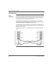
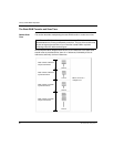
984 Theory Both the Primary and the Standby backplanes contain a CHS 110 Hot Standby
module. The modules monitor their own controller CPU and communicate with each
other via fiber link. The Primary controller keeps the Standby informed of the current
state of the application by transferring state RAM values to the Standby controller
during every logic scan. RIO head communications are also verified.
Stages of State
RAM Transfer
A Hot Standby system transfers state RAM data from the Primary to the Standby
controller while the Primary controller scans and solves the ladder logic application
program. There are three steps in this transfer process:
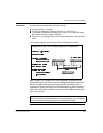
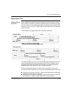
State RAM
Transfer
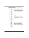
The Primary CHS 110 Hot Standby module initiates the state RAM transfer
operation. The module requests specified state RAM information from the Primary
controller.
At the beginning of each scan, the Primary controller transfers the current state RAM
data to the CHS 110 Hot Standby module.
As soon as the transfer (controller-to-CHS 110) finishes, the Primary controller
resumes scanning user logic and servicing I/O. The state RAM data is
simultaneously transferred from the Primary CHS 110 module to the Standby CHS
110 module over the fiber optic link at a rate of 10 megabaud. In turn, the Standby
CHS 110 module transfers the state RAM data to the Standby controller.
1 Primary controller-to-Primary CHS 110 state RAM transfer.
2 Primary CHS 110-to-Standby CHS 110 state RAM transfer.
3 Standby CHS 110-to-Standby controller state RAM transfer.
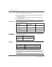
Note: Schneider Electric defines State RAM as RAM memory that is used to hold
register and discrete inputs and outputs and internal data storage. State RAM is
allocated to the four different reference types: 0xxxx, 1xxxx, 3xxxx, and 4xxxx.