


Using a Quantum 984 HSBY System
840 USE 106 00 January 2003 75
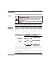
Using CHS Instruction Block
CHS Instruction
Block
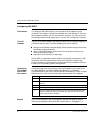
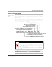
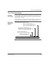
The command register is defined in the top node of the CHS instruction block. The
bits in this register are used to configure and control various parameters of the Hot
Standby system.
The command register must be a 4x register in the portion of the state RAM transfer
area that is transferred from the Primary to the Standby controller on every scan. It
also must be outside of the nontransfer area.
The values set for the bits in this register determine the system parameters at
startup. The register can be accessed while the system is running using a reference
data editor (RDE) or a Zoom screen on the CHS instruction in ladder logic.
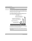
13579111315
Disables keyswitch override = 0
Enables keyswitch override = 1
Sets Controller A to OFFLINE mode = 0
Sets Controller A to RUN mode = 1
Sets Controller B to OFFLINE mode = 0
Sets Controller B to RUN mode=1
Forces standby offline if there is a logic mismatch = 0
Does not force standby offline if there is a logic mismatch = 1
Allows exec upgrade only after application stops = 0
Allows exec upgrade without stopping application = 1
0 = Swaps Modbus port 1 address during switchover
1= Does not swap Modbus port 1 address during switchover
0 = Swaps Modbus port 2 address during switchover
1 = Does not swap Modbus port 2 address during switchover
0 = Swaps Modbus port 3 address during switchover
1 = Does not swap Modbus port 3 address during switchover
2 4 6 8 10 12 14 16
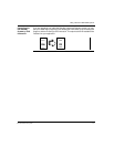
CAUTION
Hot Standby Command Register Hazard
Take precautions to be sure the register you select as the Hot Standby
command register is reserved for this purpose and not used for other
purposes in ladder logic.
Failure to follow this precaution can result in injury or equipment
damage.