


Overview of Quantum Hot Standby
840 USE 106 00 January 2003 17
Hardware Components in a Quantum Hot Standby System
Components A Quantum Hot Standby system requires two backplanes, each with at least four
slots. The backplanes must be equipped with identical, compatible Quantum:
Programmable logic controller
Remote I/O head processor
CHS 110 Hot Standby module
Cables (See
Fiber Optic Cable Guide, p. 213
)
Power supply
Other components, (Backplanes, I/O Modules, Splitters, as required)
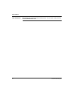
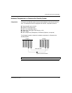
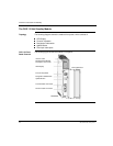
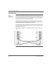
The following illustration shows the hardware components in a Quantum Hot
Standby System.
Note: The order of the modules in the backplanes must be the same.
Primary
Standby
Fiber Optic Link
Cable to the RIO Network
PS PLC RIO CHS PS PLC RIO CHS