


Theory of IEC HSBY Operation
48
840 USE 106 00 January 2003
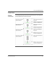
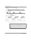
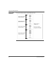
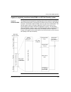
Transfer diagram The following shows a transfer diagram:
Comm DiagIEC Logic Solve Comm DiagIEC Logic Solve IEC Logic Solve Diag
1 Scan
State RAM & IEC
Heap download
128K
bytes
128K
bytes
128K
bytes
State RAM & IEC
Heap download (Over the
Fiber Optic HSBY link)
128K
bytes
128K
bytes
128K
bytes
Diag Diag DiagCommComm
State RAM & IEC
Heap download
1 Scan
CPU
CHS
CPU
Primary Rack
Standby Rack
CHS
Note: The size of 128K bytes state RAM memory in the timing diagram being
transferred with each scan is not a fixed value. It expresses the maximum amount
of data handled by the CHS module during a data transfer. This is a hardware
limitation. Therefore, the maximum State RAM limitation for the IEC user is 128 K
bytes. Unlike a 984 HSBY system, the Standby controller doesn’t solve any logic.
With the new execs delivered with Concept 2.5, the Standby Controller solves logic
in Section 1.