


CAUTION: If it is necessary to change the time of the first test
)
6.
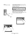
The red LED (DS1) on the Digital communicator
should
be blinking to show normal operation. The LED will not
light
if there
is
no DC power. A steady LED means the
Watchdog circuit has detected a processor or memory
problem.
Reset the watchdog with the AT&T Model
8710 Digital communicator Programmer or AT&T Model
8711 Remote Programming Package.
7.
Connect terminal to earth ground. Use a minimum 14GA
wire. The wire run should be as short and straight as
possible. Sharp angles in the wiring run reduce the
effectiveness of the ground.A good earth
ground is
essential
for phone line lightning protection.
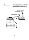
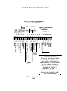
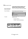
8.
Connect the phone line cord to terminal block
TB1.
T1
(grey)
= House
phone
Tip
(Seized
Tip)
T
(red)
=
incoming
Tip
R (green)=Incoming Ring
R1
(brown)
=
House
phone
Ring
(Seized
Ring)
9.
Program the Digital Communicator using the
AT&T
Model 8710 programmer or
AT&T’s
model 8711 Remote
Programming Package. Complete programming
information is available in the Digital Communicator
reference
materials located at the back of this binder.
CAUTION: The Central Controller provides a total of 600 MA to
be shared by the digital communicator, auxiliary sounding
devices, and other auxiliary devices. Do
not exceed this
total.
10. Connect the Digital Communicator.
-
Attach the power wires
to terminals
l3
and 14 of the
Central Controller.
-
Attach
communicator
channel
wires to
Central
Controller screw terminals
15
through 22.
AT&T Proprietary
information
2-24