


4
74 Series 90-70 Hot Standby CPU Redundancy User’s Guide – December 1993
GFK-0827
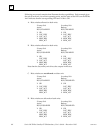
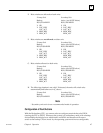
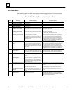
PLC Fault Table
The following table lists fault zoom Help text and messages for error codes associated
with the redundancy fault group.
Table 8. Fault Zoom Help Text for Redundancy Error Codes
Error
Code Message Fault Description Corrective Action
1 Primary Unit is Active and
Secondary Unit is Backup.
The primary and secondary units have
switched roles.
None required.
2 Secondary Unit is Active and
Primary Unit is Backup.
The secondary and primary units have
switched roles.
None required.
3 Primary Unit is Active;
No Backup Unit Available.
The primary unit has transitioned to RUN
mode and is running as a stand-alone unit.
Secondary unit MUST be placed in RUN mode with a
comparable configuration
in order to have a synchronized system.
4 Secondary Unit is Active;
No Backup Unit Available.
The secondary unit has transitioned to RUN
mode and is running as a stand-alone unit.
Primary unit MUST be placed in RUN mode with a
comparable configuration
in order to have a synchronized system.
5 Primary Unit Has Failed;
Secondary Unit is Active w/o
Backup.
Primary unit has recorded a fatal fault, has
been powered down, or has lost
ability to communicate with the secondary
unit while acting as the active or backup unit.
Secondary unit will continue running as a
stand-alone unit.
If primary unit has also logged the fault ”Secondary
Unit Has Failed: Primary Unit is Active w/o Backup”,
then communications has been broken between the
two units and must be repaired. If a fatal fault has
been logged in the primary unit, the indicated fault
must be repaired. Power may have to be cycled on one
of the units in order to re-establish communications
and return to a synchronized system.
6 Secondary Unit Has Failed;
Primary Unit is Active w/o
Backup.
Secondary unit has recorded a fatal fault, has
been powered down, or has lost ability to
communicate with the primary unit while
acting as the active or backup unit. The pri-
mary unit will continue running as a stand-
alone unit.
If secondary unit has also logged the fault ”Primary
Unit Has Failed: Secondary Unit is Active w/o Backup”,
then communications has been broken between the
two units and must be repaired. If a fatal fault has
been logged in the secondary unit, the indicated fault
must be repaired. Power may have to be cycled on one
of the units in order to re-establish communications
and return to a synchronized system.
7 Synchronization Failure; Both
Units are Active.
A communications failure between
the two units has caused each unit to become
stand-alone units. Communications has since
been restored.
One of the units should be power cycled to return to a
synchronized system. NOTE: The Genius blocks will
respond to the unit that is using Serial Bus Address 31.
8 Unable to Switch Redundancy
Roles
An attempt to switch redundancy roles was
made when it was not possible to perform the
switch.
None required.
9 Primary and Secondary Units
are Incompatible
The local unit cannot be placed in RUN mode
when its redundancy configuration is incom-
patible with the remote unit. This error is
logged when (1) Store of an incompatible con-
fig is attempted and (2) going to RUN with an
incompatible config.
Modify the configuration.
10 CPU to CPU communications
terminated
Synchronization protocol has been violated. If this fault is also accompanied by an RCM failed fault,
replace the failed RCM: otherwise power cycle the CPU
or CPUs.
11 Redundant Link has timed out The RCM has timed out while waiting on com-
munications from the other unit.
Power cycle the back-up CPU (CPU not
controlling the process); increase the fail wait time.
>11 CPU Redundancy Status has
Changed
A change in the status of the system has oc-
curred. Press Ctrl-F to determine the error
code.
Corrective action to be taken depends on the error
code.
57 Redundant link hard
failure occurred.
The RCM has been faulted due to an error
while accessing memory.
Power cycle the rack with the faulted RCM. If the
RCM’s BOARD OK LED is on, replace the cable be-
tween the RCM and the BTM. If the RCM’s BOARD
OK LED is off, replace the RCM.