


1
9GFK-0827 Chapter 1 Introduction
If the switch occurs due to a controlled condition such as toggling the unit selection
switch on the Redundancy Communications Module or forcing a switch in the user logic
program with a SVC_REQ, or because of a fault detected by the PLC CPU, then the
switch-over will occur at the beginning of the next sweep. The delay will be up to 1
sweep with the possibility of an input and an output scan after failure detection.
If the switch occurs due to a failure of the PLC CPU (including loss of power), then the
switch will occur after the backup unit determines that the active unit has failed to
rendezvous at the synchronization point. Failure to rendezvous may take up to 2 failwait
timeouts (1 for each link) to determine that a failure has occurred. Control will not
transfer, in this case, until both links have been tried unsuccessfully.
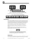
Configurable Backup Data Size
The maximum size of the backup data (Shared I/O) is 20 KBytes of Input data and 28
KBytes of Output data. The shared I/O data configuration must be the same in both the
Primary and Secondary units. This shared I/O data is transferred from the active CPU to
the backup CPU during the CPU sweep process. A total of up to 56 KBytes of user
memory is consumed by this data transfer. A maximum of 48 KBytes of the 56 KBytes is
the total Shared I/O (20 KBytes %I, %AI; 28 KBytes %Q, %M, %AQ, and %R), while the
remainder (8 KBytes) is used by the system for internal data transfers, including
synchronizing data.
On-Line Programming
On-line changes to the user logic program are permitted in both the active unit and the
backup unit. The programming device must be connected to the system in which
changes are to be made in order to make any on-line changes. Note that all precautions
regarding power source and grounding for connecting the programming device must be
followed in accordance with instructions in the Series 90-70 Programmable Controller
Installation Manual, GFK-0262.
A connection and disconnection of the parallel programmer cable should only be made
with the programmer properly grounded, and Logicmaster 90 software properly booted
up and in OFF-LINE mode. For more information, refer to the Series 90-70 Installation
manual, GFK–0262.
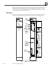
On-Line Repair
A Hot Standby CPU Redundancy system allows you to do on-line repair of failed
components without disrupting the process under control. Control status of both the
Primary and the Secondary units can be monitored by the LEDS on the Redundancy
Communications Modules in each system. When a component of the active unit fails,
control is switched to the backup unit. The failed component can then be replaced by
removing power from the rack in which it is installed.
After replacing the failed component and returning power to the rack, the backup unit
will resynchronize with the currently active unit. The unit which had failed and was
previously the active unit will determine its role in the system as part of the
resynchronization process. If it is the Primary unit (with Serial Bus Address 31) it will
once again become the active unit, the unit with Serial Bus Address 30 (Secondary unit)
will again become the backup unit. For more detailed information on replacing failed
components and resynchronization, see Chapter 4, ”System Operation”.