


4
63GFK-0827 Chapter 4 Operation
%S References for CPU Redundancy
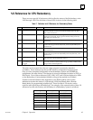
There are seven special %S references which reflect the status of the Redundancy units:
%S33 through %S39. The definition of these LEDs is shown in the following table.
Table 7. Definition for% S Reference for Redundancy Status
%S Bit Definition Nickname Description LED
%S33 Primary Unit PRI_UNT Bit will be set if the local unit is configured as the primary unit: other-
wise; it is cleared. For any given local unit, if PRI_UNT is set, then
SEC_UNT cannot be set.
no
%S34 Secondary Unit SEC_UNT Bit will be set if the local unit is configured as the secondary unit:
otherwise; it is cleared. For any given local unit, if SEC_UNT is set,
then PRI_UNT cannot be set.
no
%S35 Local Unit Ready LOC_RDY Bit will be set if local unit is ready to become the active unit; otherwise
it is cleared.
yes
%S36 Local Unit Active LOC_ACT Bit will be set if local unit is currently the active unit; otherwise it is
cleared. For any given local unit, if LOC_ACT is set, then REM_ACT
cannot be set.
yes
%S37 Remote Unit Ready REM_RDY Bit will be set if remote unit is ready to become the active unit; other-
wise it is cleared.
yes
%S38 Remote Unit Active REM_ACT Bit will be set if remote unit is currently the active unit; otherwise it is
cleared. For any given local unit, if REM_ACT is set, then LOC_ACT
cannot be set.
yes
%S39 Logic Equal LOGIC= Bit will be set if the logic program for both units in the redundant sys-
tem is the same; otherwise the bit is cleared.
no
%SB18 Redundant Informa-
tional Message, Fault
Logged
RDN_MSG Bit will be set if a redundant informational message was logged.
It can be cleared in reference tables or logic (you may want to do this
if logic will be monitoring the bit).
no
These bits can be accessed from the user’s logic program, but cannot be altered or
overridden. These references are always OFF when no configuration has been stored.
Once you have completed configuration of the Redundancy system and STORED the
configuration, the state of these %S references is set and is maintained whether in STOP or
RUN mode. Four of these references %S35, %S36, %S37, and %S38 are displayed on LEDs
on the Redundancy Communications Module, as long as that module is not faulted.
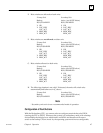
If desired, external indicators other than those on the RCM could be used as status
indicators to monitor the status of %S35 through %S38 (Local Ready/Active, Remote
Ready/Active) by programming in ladder logic. These four bits in %S memory can be
copied to other points from the ladder logic. An example of the expected status of these %S
references for each unit (Primary and Secondary) in a Redundancy system is as follows:
Description Primary Unit Secondary Unit
Primary Unit ON OFF
Secondary Unit OFF ON
Local Ready ON ON
Local Active ON OFF
Remote Ready ON ON
Remote Active OFF ON
Logic Equal ON ON