


2
section level 1 1
figure bi level 1
table_big level 1
13
GFK-0827
Chapter 2 System Components
This chapter describes the hardware components for a Hot Standby CPU Redundancy
system. It describes the modules required for the system and provides catalog numbers
of the components. For detailed installation instructions for the Series 90-70 PLC, refer
to GFK-0262, the Series 90-70 Programmable Controller Installation Manual.
Redundancy CPU
The IC697CPU780 Central Processing Unit (CPU) has been designed specifically for
Series 90-70 Hot Standby CPU Redundancy applications. This is the only Series 90-70 CPU
that currently supports CPU redundancy .
Note
It is important to note that the following features available with other
Series 90-70 CPUs are not supported by the CPU 780: I/O interrupts,
timed interrupts, the VME Integrator Racks (IC697CHS782 and
IC697CHS783), Flash Memory operation, and STOP/IOSCAN mode. In
addition, the operation of several other features is changed. For more
detailed information on these features, please see Chapter 4.
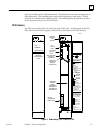
The CPU 780 supports floating point calculations, offers remote programmer keyswitch
memory protection, and has four status LEDs. Operation of this module may be
controlled by the three-position RUN/STOP switch on the module, or remotely by an
attached programmer and Logicmaster 90-70 Programming Software. Program and
configuration data can be locked through software passwords or manually by the
memory protect keyswitch. When the key is in the ”protected” position, program and
configuration data can only be changed by a programmer connected for parallel
communications (that is, to the Bus Transmitter Module).
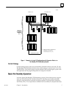
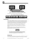
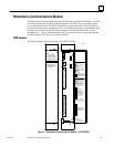
As with the other Series 90-70 CPUs, the CPU 780 must be installed in slot 1 of rack 0
(CPU rack). In a Hot Standby CPU Redundancy system, the Primary unit and the
Secondary unit must each have a Redundancy CPU installed in slot 1 of rack 0. One
CPU is configured as the Primary CPU and the other CPU is configured as the
Secondary CPU. Configuration of the CPU 780 in the Primary unit and the CPU 780 in
the Secondary unit must be done separately (see Chapter 3 for details of configuration
with the Logicmaster 90-70 configurator function). The following figure shows the CPU
location in a Hot Standby CPU Redundancy system.