


2
17GFK-0827 Chapter 2 System Components
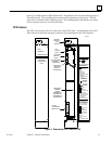
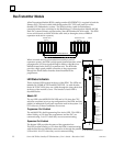
Memor y Protect Keyswitch
The Memory Protect keyswitch is located at the top of the module and has two
positions: ON and OFF. This keyswitch is used to manually lock program and
configuration data. When the key is in the ”protected” (ON) position, program and
configuration data can only be changed by a programmer connected for parallel
communications with the CPU 780 (that is, to the Bus Transmitter Module).
CPU Status LEDs
There are four LEDs mounted at the top of the CPU board which indicate the current
state of the CPU. The normal state of these LEDs when the CPU is running is ON. They
are OFF or flashing to indicate special or failure conditions.
OK
The top LED, labeled OK is an indicator of the health of the CPU. It is ON when the CPU
is functioning properly. The LED blinks when the CPU executes the power-up
diagnostics, when the system has failed, and when the remote unit is powered-up.
However, when in this state, the CPU can still communicate with the programmer (the
CPU cannot communicate with the programmer during power-up diagnostics) . The
LED is OFF when the system has failed and the CPU cannot communicate with the
programmer.
RUN
The middle LED, labeled RUN is an indicator of the RUN/STOP status of the CPU. It is
ON when the CPU is in the RUN/ENABLE or RUN/DISABLE mode. When the CPU is in
the STOP mode, the LED is OFF.
ENABLED
The bottom LED, labeled ENABLED indicates the state of the outputs. This LED is ON
when the outputs are enabled, and OFF when the outputs are disabled.
MEM PROTECT
This LED indicates the status of the memory protect keyswitch. When the keyswitch is
in the OFF position the LED is OFF, and the CPU can be programmed (if connected for
parallel communications, the CPU can be programmed regardless of the keyswitch
position). After the program has been verified, the toggle switch for mode selection can
be moved to the appropriate mode position. When the memory protect keyswitch is in
the ON position, the LED will be ON.
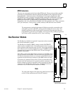
Battery Connectors
Directly below the mode switch are two identical battery connectors. The connector
wired to the lithium backup battery cable plugs into one of these connectors to connect
the battery to the CMOS memory devices. Two connectors are provided for use when
the battery requires replacement. The battery currently installed can remain connected
until the new battery is connected, thus minimizing the possibility of losing data.