


2
23GFK-0827 Chapter 2 System Components
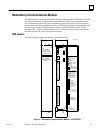
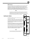
BTM Connectors
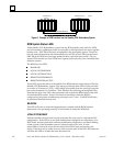
There are two connectors on the front of the BTM board. The top one provides a parallel
connection to a Work Station Interface (WSI) board installed in the programmer for the
Series 90-70 PLC. Serial connection to Workmaster II is through a programmer cable
(IC647CBL703) 10 feet (3 meters) in length (parallel connection to Workmaster is through a
parallel I/O cable, IC600WD005A). Standard parallel I/O cables are used to connect the
BTM’s lower connector to a Redundancy Communications Module in the other
Redundancy unit, or to a Bus Receiver Module in the first expansion rack. These connectors
are 37-pin connectors. The top one is a male connector, while the lower one is female.
Note
The programmer running Logicmaster 90 Software must be connected to the
same power ground as the PLC, unless special isolated drivers are used. The
parallel programmer cable should only be connected/disconnected when the
programmer is powered-up and offline. Do not power the parallel programmer
up or down while connected to a PLC that is running.
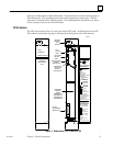
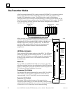
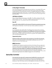
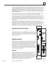
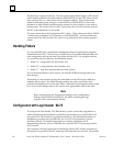
Bus Receiver Module
The Bus Receiver Module is required if expansion racks are used in
the overall redundancy system.
The Bus Receiver Module (BRM), catalog number IC697BEM711,
which must be installed in slot 1 of each expansion rack in a system,
is the expansion rack interface to the I/O bus. It provides the link to
the I/O bus for I/O modules installed in its rack. The BRM in the first
expansion rack connects to the BTM in the CPU rack through a
parallel I/O bus cable.
This cable is connected to the bottom connector on the BTM, and to
the top connector on the BRM. The next rack to be included in the
I/O bus is connected to the lower connector on the BRM in the first
expansion rack and the top connector of the BRM in the next rack.
Connection of expansion racks on the I/O bus is continued in this
manner until the maximum of 6 expansion racks is connected. The
bottom connector in the last expansion rack is connected to the top
connector of the RCM in the remote unit. Note that the last bus
connection is to an RCM module (instead of a BRM).
Note
The total cable length of all connecting cables between racks
on the I/O bus cannot exceed 50 feet (15 meters).
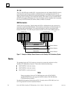
INSTALLED
CONFIGURED
a42987
MODEL 70
BEM 711
TERMINATION
EXPANSION
PORT ENABLED
ON = OK, ENABLED
MODULE
IC697BEM711
LABEL
44A726758–201
RACK
MODULE FUNCTION
SERIES 90–70
BUS RECEIVER
HIGH SPEED
INTERFACE FROM
90–70 EXPANSION
RACKS TO 90–70
MAIN RACK
USE THIS MODULE
IN FIRST SLOT ONLY
EXPANSION
PORT IN
(TOWARDS CPU)
TO BEM 711
OR BEM 713
50 FT. MAX.TOTAL
CABLE LENGTH
FROM BEM 713 TO
LAST BEM 711
EXPANSION
PORT OUT
(AWAY FROM CPU)
TO BEM 711
INSTALL
TERMINATOR
PLUG IN LAST
RACK IN CHAIN
USE IC697ACC702
BUS RECEIVER MODULE