


1
5GFK-0827 Chapter 1 Introduction
Y
Y
C
B
T
M
R
C
M
G
B
C
31
PRIMARY UNIT SECONDARY UNIT
30
B
L
O
C
K
B
L
O
C
K
S
C
A
N
N
E
R
REMOTE DROP
I
O
I
O
I
O
I
O
I
O
I
O
P
S
I
O
I
O
P
S
P
S
B
T
M
G
B
C
B
L
O
C
K
I
O
I
O
I
O
I
O
I
O
I
O
I
O
I
O
P
S
P
U
C
P
U
B
R
M
RACK 0
RACK 1
RACK 0
I
O
I
O
I
O
I
O
I
O
I
O
I
O
I
O
P
S
RACK 6
LOCAL I/0
CAN BE IN
RACKS
0 - 6
I
O
I
O
I
O
I
O
I
O
I
O
I
O
I
O
I
O
I
O
B
R
M
R
C
M
I/O CABLE WITH BUILT-IN TERMINATION
IC697CBL811 (10 FEET (3m))
IC697CBL826 (25 FEET (7.5m)
*
*
TERMINATED I/O CABLE
TERMINATED I/O CABLE
*
a47000
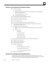
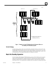
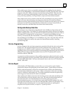
Figure 1. Example of a Local I/O Configuration with Expansion Racks in a
Hot Standby CPU Redundancy System
Control Strategy
Control strategy refers to the type of redundancy alternative that may be used. For the
Hot Standby CPU Redundancy product, the control strategy is referred to as Genius Hot
Standby (GHS). The control strategy must be selected when configuring the system with
the Logicmaster 90-70 programming Software Configurator function.
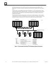
Basic Hot Standby Operation
In a basic Genius Hot Standby CPU Redundancy system, Genius blocks receive outputs
from two PLCs (Primary PLC and Secondary PLC), but they are normally controlled
directly by the Genius Bus Controller at serial bus address 31 (Genius Bus Controller in
the Primary PLC). If no output data is available from bus address 31 (the preferred data)