


2
24 Series 90-70 Hot Standby CPU Redundancy User’s Guide – December 1993
GFK-0827
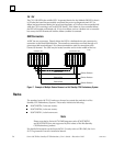
I/O Bus Signal Termination
The I/O bus signals must be terminated at the end of the bus. In a standard PLC system
this is done by installing a resistor pack, located inside of a terminator plug (catalog
number IC697ACC702) on the bottom connector of the BRM module that is installed in
the last I/O expansion rack in the system. In a Hot Standby CPU Redundancy system a
special I/O cable with built-in termination is used. Do not use the resistor plug with the
terminated cable.
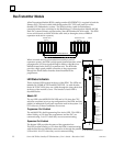
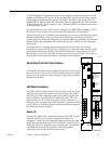
LED Status Indicators
There are three LEDs located at the top of the BRM. The LEDs are labeled: OK, LAST
RACK, and BUS ACTIVE. The LEDs are visible through the clear plastic lens at the top
of the module’s cover. The function of each LED is described below.
Board OK
The top LED, the Board OK LED, is ON when the CPU software completes its power-up
configuration of the expansion rack and at least one module in that rack responds to the
CPU requests for information. It is OFF when any of these conditions are not met.
Last Rack
The middle LED is the Last Rack LED. This LED is ON when the I/O bus terminator
plug is installed in the bottom connector of this BRM, and is Off when it is not installed.
The terminator plug is to be installed only on the BRM that is at the end of the expansion
rack I/O bus. All BRMs are shipped from the factory with a terminator plug installed.
These terminator plugs must be removed from any expansion rack located between the
CPU rack and the last expansion rack.
Expansion Bus Active
The bottom LED provides the status of the expansion bus. This LED is ON when the
BRM has detected that there has been activity on the expansion bus in the last 500 ms,
otherwise it is off. When this LED is OFF, the BRM is holding the Series 90-70 I/O
modules in its rack in their default state.
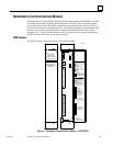
BRM Connectors
The BRM has two connectors mounted on the front of the board. The top connector is
for the I/O cable connection to either the lower connector on a BTM in the CPU rack, or
to the lower connector on another BRM. The lower connector is for an I/O cable
connection to the upper connector of a BRM in the next expansion rack on the I/O bus or
to the top connector on an RCM. The I/O cable is an 18 twisted-pair cable with a ground
shield. The total maximum cable length from the CPU rack to the most distant
expansion rack (at the same ground potential) is 50 feet. Standard parallel I/O bus cables
that meet this specification are available in lengths of 5, 10, 25, and 50 feet.
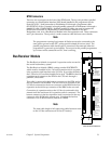
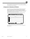
Genius Bus Controller
The Genius Bus Controller (GBC), catalog number IC697BEM731, for the Series 90-70
PLC is the interface for the Series 90-70 PLC to a Genius I/O communications system.
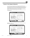
Configuration of the GBC is simple through use of Logicmaster 90 Configurator
software. Genius I/O blocks are scanned asynchronously by the GBC and I/O data is
transferred to the CPU once per scan over the backplane of the Series 90-70 PLC rack.