


2
16 Series 90-70 Hot Standby CPU Redundancy User’s Guide – December 1993
GFK-0827
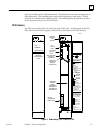
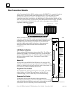
CPU Mode Switch
A three-position toggle switch is mounted near the top of the CPU board. This switch
selects one of three operating modes for the CPU: RUN/ENABLED, RUN/DISABLED, or
STOP. Although the mode of operation for the CPU can be controlled from both the
switch and the programmer, the switch position restricts the ability of the programmer
to put the CPU into certain modes.
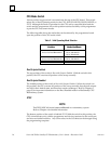
The following table shows the modes that can be selected by the programmer based
upon the position of the CPU mode switch.
Table 2. Valid Operating Mode Selection
CPU Mode Switch
Position
Allowable Programmer
Mode Command
CPU Mode Switch
Position
Allowable Programmer
Mode Command
STOP
RUN/OUTPUTS ENABLED RUN/DISABLED
RUN/ENABLED
STOP
RUN/OUTPUTS DISABLED RUN/DISABLED
STOP STOP
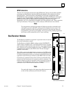
Run/Outputs Enabled
The top position of the switch is Run with Outputs Enabled. With the switch in this
position, the CPU executes all portions of the sweep normally.
Run/Outputs Disabled
The middle position of the switch is Run with Outputs Disabled. When the switch is in
this position, the CPU executes all portions of the sweep normally, but physical outputs
are held in their default state, and therefore remain unchanged. Refer to Chapter 4,
page 65 for important information on the Run/Disabled mode in a Hot Standby CPU
Redundancy system.
STOP
NOTE
The STOP/IOSCAN mode is not a valid mode in a redundancy system.
Refer to Chapter 4 for detailed information.
The bottom position of the switch is labeled STOP. With the switch in this position, the
CPU communicates only with the programmer and devices connected to the serial port,
and recovers faulted modules. Any of the values in the I/O tables can be changed using
the programming computer.