


3
30 Series 90-70 Hot Standby CPU Redundancy User’s Guide – December 1993
GFK-0827
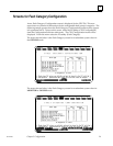
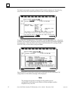
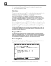
The Fault Type is shown at the left. The first column under Fault Category (CFG) shows
which faults are FATAL and which faults are DIAGNOSTIC for this CPU, when it is the
only running CPU (i.e., stand-alone with no backup available). This column can be
edited for each fault group/category to select FATAL or DIAGNOSTIC so that a safe
shutdown or fault tolerant operation can be selected for when a failure occurs with no
backup ready. The column next to it (PLC) shows the value (F or D) currently stored to
the PLC or the defaults if it is not stored.
The next column shows the Synchronized PLC values. These values are either F (FATAL
- which causes a transition to STOP mode), or D (DIAGNOSTIC - which maintains the
current state of the PLC) for this CPU, when it is synchronized. This column cannot be
edited.
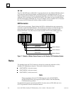
Handling Folders
It is very desirable from a maintenance standpoint to keep the applications programs
identical between PLCs. The best way to handle this is to maintain different folders for
each configuration and use the same logic folder for both PLCs. By using this scheme,
you would have three folders for the redundant system.
1. Folder ”A” - configuration for the Primary unit.
2. Folder ”B” - configuration for the Secondary unit.
3. Folder ”C” - logic and reference tables for both systems.
It is recommended that for a new system, you should STORE the configuration first,
then the logic.
Functionally, it is not necessary to keep the same ladder in both PLCs but it is difficult to
maintain such a system. Any ladder changes made in one system would have to be
evaluated and hand-keyed in to the other folder. Other than visual inspection, there would
be no way to tell if changes made in one system were appropriately made in the other.
Note
When entering either the Programmer Package or the Configuration
Package while ONLINE and EQUAL, the folder containing the logic
program will be automatically selected.
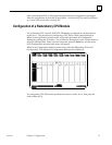
Configuration with Logicmaster 90-70
To configure the Hot Standby CPU Redundancy system, connect the programmer to
either the Bus Transmitter Module for parallel communications or to the RS-485 serial
port on the CPU 780 module for serial communications. For detailed information on
installation procedures refer to GFK-0262, the Series 90-70 Programmable Controller
Installation Manual. For detailed information on running Logicmaster 90-70
Programming Software, refer to GFK-0263, the Logicmaster 90-70 Programming Software
User’s Manual.
Any computer running Logicmaster 90 interfacing with the PLC must be connected to
the same power ground as the PLC unless special isolated drivers are used. The parallel