


3
37GFK-0827 Chapter 3 Configuration
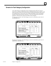
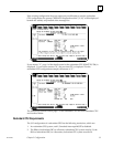
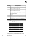
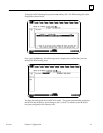
Table 4. Shared I/O Data Parameters
I/O Parameter Description and Valid Entries
%I Ref Adr Starting address for redundant %I data region. Range is %I00001...%I12288. The starting
address is bit aligned. Default value is %I00001.
%I LENGTH The bit length of the redundant %I data region. Range is 0...12288. Default value is 0.
%Q Ref Adr Starting address for redundant %Q data region. Range is %Q00001...%Q12288. The
starting address is byte aligned. Default value is %Q00001.
%Q LENGTH The bit length of the redundant %Q data region. Range is 0...12288. Default value is 0.
%M Ref Adr Starting address for redundant %M data region. Range is %M00001...%M12288. The
starting address is byte aligned. Default value is %M00001.
%M LENGTH The bit length of the redundant %M data region. Range is 0...12288. Default value is 0.
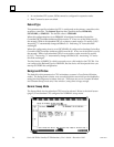
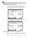
%R Ref Adr Starting address for redundant %R data region. Range is %R00001...%R configured limit or
8K, whichever is smaller (since only 28 Kbytes can be transferred). The %R memory limit
for the CPU 780 is configurable in the PLC memory configuration screen. The maximum
limit depends on the available CPU memory. See ”Memory Configuration” later in this
chapter. The default value is %R00001.
%R LENGTH The word length of the redundant %R data region. Range is 0...%R configured limit. The
default value is 0.
%AI Ref Adr Starting address for redundant %AI data region. Range is %AI00000...%AI configured
limit. The %AI memory limit for the is configurable in the PLC memory configuration screen.
The maximum limit depends on the available CPU memory. The default value is %AI00001.
%AI LENGTH The word length of the redundant %AI data region. Range is 0...%AI configured limit.
The default value is 0.
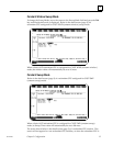
%AQ Ref Adr Starting address for redundant %AQ data region. Range is %AQ00000...%AQ configured limit.
The %AQ memory limit for the is configurable in the PLC memory configuration screen. The
maximum limit depends on the available CPU memory. The default value is %AQ00001.
%AQ
LENGTH
The word length of the redundant %AQ data region. Range is 0...%AQ configured limit.
Default value is 0.
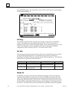
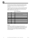
Table 5. Shared I/O Reference Values
Parameter Valid Values Default Values
%I Ref Adr %I00001...%I12288 %I00001
%I Length 0...12288 0
%Q Ref Adr %Q00001...%Q12288 %Q00001
%Q Length 0...12288 0
%M Ref Adr %M00001...%M12288 %M00001
%M Length 0...12288 0
%R Ref Adr %R0001..configured limits %R00001
%R Length 0...PLC memory limits 0
%AI Ref Adr %AI0001..configured limits %AI00001
%AI Length 0...configured limits 0
%AQ Ref Adr %AQ0001..configured limits %AQ00001
%AQ Length 0...configured limits 0
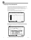
Transfer Data Size
The following table shows the amount of Shared I/O data transferred for each reference
type. No more than 20 Kbytes of Input data and 28 Kbytes of Output data can be
transferred (an additional 8 Kbytes is reserved for resynchronization transfers).