


2
22 Series 90-70 Hot Standby CPU Redundancy User’s Guide – December 1993
GFK-0827
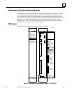
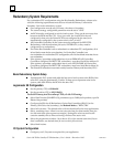
Bus Transmitter Module
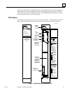
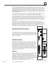
A Bus Transmitter Module (BTM), catalog number IC697BEM713, is required in both the
Primary PLC CPU rack (rack 0) and the Secondary PLC CPU rack (rack 0) in a Hot
Standby CPU Redundancy system. The BTM provides a path for Redundancy
communications when connected to the Redundancy Communications Module (RCM).
Each PLC system (Primary and Secondary) has a BTM and an RCM in rack 0. The BTM
in one unit connects to the RCM in the other unit (or through a series or BRMs if
expansion racks are in a system).
C
B
T
M
R
C
M
31
PRIMARY UNIT SECONDARY UNIT
30
P
S
P
S
B
T
M
R
C
M
Redundancy Communications Link
Redundancy Communications Link
G
B
C
G
B
C
P
U
C
P
U
( RACK 0 )
( RACK 0 )
a47006
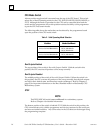
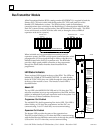
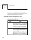
When included as a bus communications module in an I/O
expansion system, the BTM is a high speed parallel interface which
propagates the I/O bus signals through a cable to a Bus Receiver
Module located in the first I/O expansion rack. The BTM also
provides a high speed parallel connection to the programmer
through the Work Station Interface board installed in the
programmer.
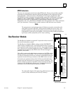
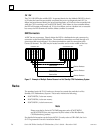
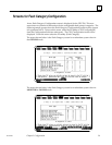
LED Status Indicators
There are three LEDs located at the top of the BTM. The LEDs are
labeled: OK, PGMR ACTIVE and BUS ACTIVE. As with all other
Series 90-70 PLC LEDs, they are visible through the clear plastic lens
at the top of the module’s cover. The function of each LED is
described below.
Module OK
The top LED is the MODULE OK LED and is ON when the CPU
software completes its power-up configuration of the BTM, and has
polled (or attempted to poll) each expansion rack in the system. It is
OFF when any of these conditions are not met.
Programmer Port Enabled
The middle LED is the Programming Port Active LED. This LED is
either blinking or ON when the programmer and the PLC are
communicating. It is OFF when they are not communicating.
Expansion Port Enabled
The bottom LED provides the status of the expansion bus.
This LED is either blinking or ON when the BTM is communicating
with the Bus Receiver Modules connected to it through the parallel
I/O bus link. It is OFF when they are not communicating.
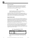
a42986
MODEL 70
BEM 713
MODULE OK
PROGRAMMER
EXPANSION
PORT ENABLED
PORT ENABLED
ON = OK, ENABLED
MODULE FUNCTION
SERIES 90–70
BUS TRANSMITTER
HIGH SPEED
INTERFACE TO
PROGRAMMER AND
90–70 EXPANSION
RACKS.
50 FT. MAXIMUM TOTAL
CABLE LENGTH TO
LAST BEM 711
MODULE
IC697BEM713
LABEL
44A726758–103
PARALLEL
PARALLEL
PORT
PROGRAMMER
ONLY
50 FT. MAXIMUM
CABLE LENGTH
EXPANSION
PORT
TO BEM 711
(7 DROPS
MAXIMUM)
BUS TRANSMITTER MODULE