


1
8 Series 90-70 Hot Standby CPU Redundancy User’s Guide – December 1993
GFK-0827
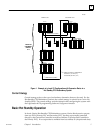
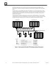
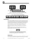
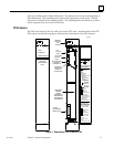
the two CPUs and provides the communications path for the transfer of I/O data
between the two units. An RCM must be configured in both the Primary PLC and the
Secondary PLC. The RCM must reside in the CPU rack (rack 0) in a system and there
can be no empty slot between the RCM and the CPU (there can be other modules).
Bumpless Switching
Bumpless switching occurs when the active unit fails and system control is transferred to
the backup unit without affecting the operation of the process under control.
Synchronized CPUs
For bumpless switching to occur, the CPU in the active and backup units must operate in a
synchronous fashion, that is, the operation of both units must occur at the same time (or as
close to the same time as possible). There are two synchronization points in the sweep: one
immediately after the input scan and the other immediately before the output scan.
Synchronization data is passed from the active to the backup unit at the first
synchronization point, which occurs after the input scan. Specifically, after the inputs are
scanned, the inputs that were just read (%I and %AI) are sent from the active to the backup
unit and the synchronization message is passed after the input data.
The second synchronization point occurs immediately after the end of the logic solution
before the output scan begins. During this time, all remaining control data, including the
%Q, %AQ, %M and %R memories is transferred from the active unit to the backup unit.
Effect on Scan Time
When a system is operating normally (no faults exist in the system) redundancy adds about
21 ms (includes 5 ms default background window setting) per PLC scan. The effect on scan
time depends on the system configuration. The following number of data points and
registers is considered the base configuration on which the 21 ms was calculated.
512 %I, 512 %Q, 512 %M
256 %AI, 256 %AQ
2048 %R
Each additional 1K %I, %Q, or %M data points adds about 1.8 ms to the scan impact
(add 25% for each %I or %Q reference if point faults enabled) and each additional 1K of
%R, %AI, or %AQ registers adds about 5 ms to the scan impact (add 50% for each %AI
or %AQ reference if point faults enabled).
Fail Wait Time
When the active CPU has a failure, the backup CPU will wait for a specified time (in
milliseconds) before assuming that the link has failed. This time is referred to as the Fail
Wait time. The duration of this time must be specified during configuration of both the
Primary and Secondary units and can range from 60 ms to 400 ms (in increments of 10
ms), with the default value being 60 ms.
Switch to Backup Unit Time
The amount of time it takes to switch control from the active unit to the backup unit
depends on what caused the switch to take place.