


4
66 Series 90-70 Hot Standby CPU Redundancy User’s Guide – December 1993
GFK-0827
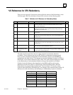
Following are several examples that illustrate the above guidelines. Each example gives
the role of each unit, its current operating mode, and the state of the LEDs on the RCMs.
An X indicates that the corresponding LED and %S bit is ON.
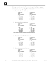
A. Role switches allowed on both units.
Primary Unit Secondary Unit
Active Backup
RUN/ENABLED RUN/ENABLED
XOK XOK
X LOC_RDY X LOC_RDY
X LOC_ACT LOC_ACT
X REM_RDY X REM_RDY
REM_ACT X REM_ACT
B. Role switches allowed on both units.
Primary Unit Secondary Unit
Active Backup
RUN/DISABLED RUN/ENABLED
XOK XOK
LOC_RDY X LOC_RDY
X LOC_ACT LOC_ACT
X REM_RDY REM_RDY
REM_ACT X REM_ACT
Note that the Secondary unit drives the outputs in this case.
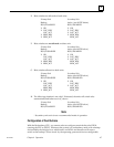
C. Role switches are not allowed on either unit.
Primary Unit Secondary Unit
Active Backup
RUN/ENABLED RUN/DISABLED
XOK XOK
X LOC_RDY LOC_RDY
X LOC_ACT LOC_ACT
REM_RDY X REM_RDY
REM_ACT X REM_ACT
D. Role switches are allowed on both units.
Primary Unit Secondary Unit
Active Backup
RUN/DISABLED RUN/DISABLED
XOK XOK
LOC_RDY LOC_RDY
X LOC_ACT LOC_ACT
REM_RDY REM_RDY
REM_ACT X REM_ACT