


1
7GFK-0827 Chapter 1 Introduction
Redundancy CPU Module
The same model of CPU must be installed in both the Primary and Secondary PLCs.
This CPU, which is the only CPU that currently supports synchronized Hot Standby
CPU redundancy, is the CPU 780 (catalog number IC697CPU780). This CPU is similar to
the existing IC697CPU782 CPU in that it has an 80386DX microprocessor which operates
at a speed of 16 MHz, supports floating point calculations, and requires an expansion
memory board which can be 128 KBytes, 256 Kbytes with 256 KBytes of non-volatile
flash memory, 256 KBytes or 512 KBytes.
NOTE
It is important to note that the following features available with other
Series 90-70 CPUs are not supported by the CPU 780: I/O interrupts,
timed interrupts, the VME Integrator Racks (IC697CHS782 and
IC697CHS783), Flash memory operation, and STOP/IOSCAN mode. In
addition, the operation of several other features is changed. For more
detailed information on these features, please see Chapter 4.
As with the other Series 90-70 CPUs, the CPU 780 must be installed in slot 1 of rack 0
(CPU rack). The Primary unit and the Secondary unit must each have a Redundancy
CPU installed in slot 1 of rack 0 with one CPU configured as the Primary CPU and the
other CPU configured as the Secondary CPU. Configuration of the CPU 780 in the
Primary unit and the CPU 780 in the Secondary unit must be done separately (see
Chapter 3 for details of configuration with the Logicmaster 90-70 configurator function).
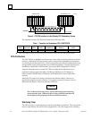
Redundancy Communications Module
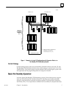
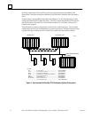
The Redundancy Communications Module (RCM), catalog number IC697RCM711,
provides a path (see Figure 1) for sharing data between the two CPUs in the redundant
system. The RCM has five LEDS:
BOARD OK
LOCAL SYSTEM READY
LOCAL SYSTEM ACTIVE
REMOTE SYSTEM READY
REMOTE SYSTEM ACTIVE.
These LEDs report the status of the health of the RCM and the control status of the Hot
Standby CPU Redundancy system. The status provided by these LEDs is also provided
in an area of %S memory (%S33 through %S39) which is accessible from the user logic
program but cannot be altered or overridden.
The module has a momentary pushbutton switch which when depressed for 1 second
and released allows you to manually switch control from the active unit to the standby
unit. The switch between units can also be controlled through user logic
implementation of a SVC_REQ function that is activated by a discrete input point. Both
of these switch requests may only be made every 10 seconds.
In a synchronized system, I/O data is controlled by only one unit (the active unit) but is
shared between both units (active and backup units). The RCM provides the path for a
synchronizing message from the active to the backup unit which is used to synchronize