


2
25GFK-0827 Chapter 2 System Components
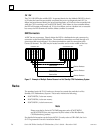
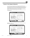
The Hot Standby CPU Redundancy system uses a single Genius bus and requires one GBC
module in the Primary PLC and one in the Secondary PLC; however there can be multiple
Genius busses configured in this manner in a system. The GBCs in the Primary PLC are
assigned SBA 31, and the GBCs in the Secondary PLC are assigned SBA 30. Data from SBA
31 in the Primary PLC is the ”preferred” data. The Primary PLC is normally the active unit
in the redundancy system.
In a redundancy system the GBCs must be configured for ”RED CTRL” redundancy. All of
the Genius devices on the Genius bus must also be configured for ”Redundancy”
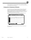
The bus can have up to 30 Genius devices connected to it, with one of the SBAs reserved for
the Hand-Held Monitor. Any type of Genius I/O block may be connected to this bus. A
Genius I/O device will use the output data received from SBA 31 in preference to data from
SBA 30. If the active and backup units switch roles, the GBC will then use the output data
from SBA 30.
As a safety feature, a watchdog timer protects each Genius I/O link. This timer is
periodically reset by the GBC software, Should it ever expire, the microcontroller on the
board ceases functioning and the Channel OK LED turns off. If this happens in a CPU
Redundancy system, the other GBC will then drive the Genius I/O blocks The cause of
the link failure must be determined to re-establish communications.
Genius Bus Controller User Features
A Genius Bus Controller can be installed in any slot in rack 0, except
for slot 1 which is reserved for the CPU module. It can be installed
in any slot in an expansion rack, except slot 1 which must contain a
Bus Receiver Module.
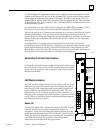
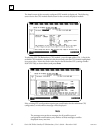
LED Status Indicators
The GBC has three LEDs located at the top of the board: one as an
indicator of the state of the board, and one to indicate the state of
the Genius I/O link. When the board is functionally properly, the
top two LEDs are ON (third LED currently not used). They are
either blinking or OFF to indicate special or failure conditions. If,
after the power-up diagnostics routine has been completed, all LEDs
are OFF, this is an indication that a board failure has been detected
and the board must be replaced.
Module OK
The top LED, labeled OK, indicates the health of the GBC. It is ON
when the board has successfully completed the power-up
diagnostics. If the power-up diagnostics detects a failure or if the
board fails during operation, the LED will be OFF. The LED blinks
during the power-up diagnostics and when the GBC is installed in
a slot different from the slot specified by the configuration
information downloaded from the programmer.
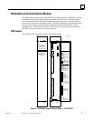
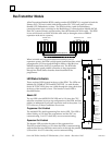
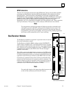
a42985
MODEL 70
BEM 731
MODULE OK
CHANNEL 1 OK
NOT USED
ON = OK
MODULE
IC697BEM731C
LABEL
44A726758–11
MODULE FUNCTION
SERIES 90–70
GENIUS BUS
CONTROLLER
Removal of terminal
block breaks bus if
external jumpers are
not applied as shown
CHANNEL 1
SER 1
SER 2
SHIELD
OUT
N
C
N
C
N
C
N
C
N
C
N
C
( 1 CHANNEL )
SER 1
SER 2
SHIELD
IN
HAND HELD
MONITOR
CHANNEL 1
GENIUS BUS CONTROLLER