


1
4 Series 90-70 Hot Standby CPU Redundancy User’s Guide – December 1993
GFK-0827
I/O Systems for Hot Standby CPU Redundancy Systems
Both Series 90-70 Local I/O and Genius I/O systems can be present in a Hot Standby
CPU Redundancy control system. The two units are not required to have matching I/O
systems. They may have different numbers of I/O racks, and different local I/O or
option modules.
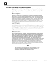
Genius I/O System
A Genius I/O system is the I/O system that is included in the redundancy system as
shown below. The system can have multiple Genius I/O buses. Any Genius device can
be placed on the bus (Genius blocks, Remote I/O Scanner, etc.). The Genius devices are
under control of the active unit in the Redundancy system. The Genius Bus Controller
in the Primary Unit has a Serial bus Address of 31; the Genius Bus Controller in the
Secondary Unit has a Serial Bus Address of 30. Data from Serial Bus Address 31 is the
preferred data when data is being sent from both units to devices on the Genius bus.
Local I/O System
Local I/O can be configured in the overall PLC system; however, it is not part of the Hot
Standby CPU Redundancy system. Control of Local I/O is done normally through the
user’s logic program. The user may choose to transfer or not transfer this data. A failure
in the Local I/O system will affect the system as described in GFK-0265, the Series 90-70
Programmable Controller Reference Manual.
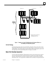
Cable Connections
The I/O system is configured ”normally” except as described below (see the following
figure). That is, a Bus Transmitter Module configured in rack 0 is connected through a
parallel I/O cable to a Bus Receiver Module in the next rack. The link is continued from
this Bus Receiver Module to the Bus Receiver Module in the next rack. This link is
continued with a maximum of six expansion racks. Then, the last Bus Receiver is
connected via an I/O cable with built-in termination (catalog IC697CBL811 (10 feet (3m))
or IC697CBL826 (25 feet (7.5m)). The last module in the parallel I/O bus link must be a
Redundancy Communications Module (RCM). This terminated I/O cable allows
replacement of the RCM without interrupting the running system. If no expansion
racks are used, the terminated I/O cable is connected directly from the Bus Transmitter
Module to the Redundancy Communications Module.
Note
The exception to a normally configured system is that Rack 7, which
normally can contain I/O modules is not available for physical I/O
modules in a Hot Standby CPU Redundancy system.