


2
21GFK-0827 Chapter 2 System Components
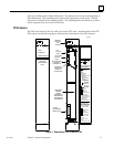
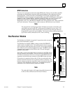
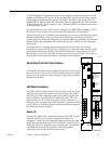
LOCAL SYSTEM ACTIVE
Indicates whether the local unit is the controlling (or active) unit in a redundancy
system. It is the responsibility of the local unit to set the state of this LED at least once
during each sweep; if the local unit is unable to set (or fails to set) the state of the LED,
the hardware will force the LED to off after the timer has timed out.
REMOTE SYSTEM READY
Indicates whether the remote unit is ready to become the active unit in a redundant PLC
configuration. If the LED is on, the remote unit has been configured for redundancy, is
in RUN mode, and has performed sufficient initialization, diagnostics, and
hand–shaking to take control of the redundant system if selected as the active unit. It is
the responsibility of the remote unit to set the state of this LED at least once during each
sweep; if the remote unit is unable to set (or fails to set) the state of the LED, the
hardware will force the LED to off after the timer has timed out.
REMOTE SYSTEM ACTIVE
Indicates whether the remote unit is the controlling (or active) unit in a redundancy
scheme. It is the responsibility of the remote unit to set the state of this LED at least once
during each sweep; if the remote unit is unable to set (or fails to set) the state of the LED,
the hardware will force the LED to off after the timer has timed out.
Unit Selection Pushbutton
The module has a momentary pushbutton switch which when depressed for 1 second
and released allows you to manually switch control from the active unit to the backup unit
if the backup unit is READY. The status of each pushbutton is checked by the PLC CPU
software. The switch between units can also be controlled through user logic
implementation of a SVC_REQ function that is activated by user logic. After a switch
has been requested, you must wait 10 seconds before requesting another switch.
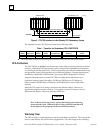
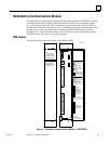
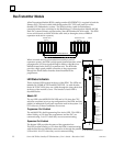
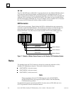
RCM Connectors
The RCM has two connectors mounted on the front of the board. The top connector is the
only one used. It is connected via an I/O cable with built-in termination to the last rack of
the other PLC system. If no expansion rack is used, it is connected to the lower connector
on the Bus Transmitter Module of the other system. The I/O cable with built-in
termination is available in two lengths:
IC697CBL811, 10 feet (3 meters)
IC697CBL826, 25 feet (7.5 meters)