


3
28 Series 90-70 Hot Standby CPU Redundancy User’s Guide – December 1993
GFK-0827
Redundancy System Requirements
For a redundant CPU configuration using the Hot-Standby Redundancy scheme to be
valid, the following requirements must be true in both the Primary Unit and the
Secondary Unit in the redundancy system.
One configuration must be set to Primary; the other to Secondary.
The control strategy configurable parameter must be set to ”GHS”.
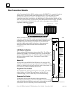
An RCM must be configured in rack 0 of each system. There can be no empty slots
between the RCM and the CPU. For a given unit, the Local RCM is the one
configured in that unit; the Remote RCM is not configured by the user, but is
automatically configured by the system to be in slot 1 of rack 7.
All Genius Bus Controllers in the system must be configured for RED CTRL
Redundancy with the redundant pair set for EXTERNAL, or they must be
configured for no redundancy.
If a Genius Bus Controller is set to redundant in a redundant CPU configuration, all of
its bus blocks must also be set redundant; if a Genius Bus Controller is set
non-redundant in a redundant CPU configuration, all of its bus blocks must also be set
non-redundant.
If the primary/secondary configurable item is set to PRIMARY, all Genius Bus
Controllers configured for RED CTRL redundancy must have Serial Bus Address 31.
If the primary/secondary configurable item is set to SECONDARY, all Genius Bus
Controllers configured for RED CTRL redundancy must have Serial Bus Address 30.
The Shared I/O selections must match exactly between Primary and Secondary PLCs.
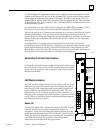
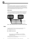
Basic Redundancy System Setup
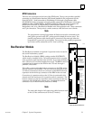
Assemble each PLC system and cable the last rack of each system to the RCM of the
other PLC using the terminated I/O cable. If there are no expansion racks in the
system, cable each BTM to the RCM in the other PLC.
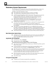
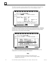
Logicmaster 90 Configuration
Set the primary CPU to PRIMARY.
Set the secondary CPU to SECNDARY.
For both Primary and Secondary CPUs, do the Following:
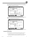
Select Data Transfer (SHARED I/O) parameters (up to 20 Kbytes Input data, up to 28
Kbytes Output data).
Configure the SBA for all Redundancy Genius Bus Controllers (SBA 31 for the
Primary; SBA 30 for the Secondary), and Redund Mode to ”RED CTRL”.
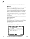
Select fail-wait time. The default value of 60 ms should suffice for most applications.
Select watchdog timer. Allow for worst case scan time plus data transfer time plus
two fail-wait times (plus a generous margin). Setting this value too small could
cause the standby unit to time out during a failure of the active unit.
Select the programmer window. Set to about 10% of the normal scan time (if scan
time is unknown, use default time (do not exceed the fail wait time).
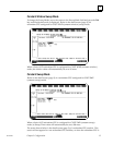
Select Fault Actions.
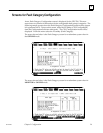
I/O System Configuration
Configure your I/O system as required for your application.