


1
2 Series 90-70 Hot Standby CPU Redundancy User’s Guide – December 1993
GFK-0827
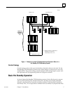
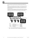
contains all redundant Genius Bus Controllers at Serial Bus Address 31; the Secondary
PLC contains all redundant Genius Bus Controllers at Serial Bus Address 30. The CPU
that currently controls the system is called the active unit, the other CPU is the standby
unit.
If certain system failures are detected in the active unit, control is switched to the
standby unit. Control can also be switched by depressing a pushbutton on the
Redundancy Communications Module, or through the user’s logic program. When a
switch of control occurs, the units switch roles; the active unit becomes the standby unit
and the standby unit becomes the active unit.
Each PLC must have a Redundancy CPU module (catalog number IC697CPU780) and a
Redundancy Communications module (IC697RCM711) which provides the synchronization
link between the two units, (and a Bus Transmitter Module (IC697BEM713)). The
scanning process of both CPUs is synchronized to keep active and standby units in
lockstep to minimize ”bumps” or upsets to the process when switching from the active
to the standby unit. The effect of this action is a bumpless switch.
The Series 90-70 CPU Redundancy system runs synchronously with a transfer of all
control data that defines machine status and any internal data needed to keep the two
CPUs operating in sync, and is capable of executing the same program and obtaining the
same results. The transfer of data from the active unit to the standby unit occurs once
per sweep. These CPU to CPU transfers are checked for data integrity.