


4
60 Series 90-70 Hot Standby CPU Redundancy User’s Guide – December 1993
GFK-0827
The transfer of the redundancy data during each sweep will be in blocks with each block
checked for data integrity. The transferred data will be held in a temporary area by the
backup CPU until all data has been received and verified from the active unit. Then the
backup CPU will copy that data from the temporary area to the actual PLC memories.
The transfer is capable of being performed on either RCM link. If one RCM link fails
then the transfer will switch to the other RCM without causing a loss of synchronization
in the system. If at any time during a transfer the active unit fails or the full transfer fails
to complete properly (both RCMs fail) then the backup unit will disregard the data that
has been transferred to the temporary area and proceed with the values it already
obtained during its input scan.
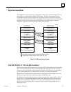
The last part of the input data transfer is the synchronizing message containing the
”Start of Sweep Time”. The ”Start of Sweep Time” is the universal start of sweep time
for the redundancy system. Normally each PLC CPU operates its elapsed time clock on
which timers are based independently and the clocks are always started over from zero
on a power cycle. Two independent clocks would cause time discontinuity at switch
over time. In addition the clocks will tend to drift from each other over time. The
redundancy system corrects for this by keeping a single elapsed time value for the entire
redundancy system. The time will be continuous as long as one of the two systems
continue to run and the active unit will continuously pass the time to backup unit to
correct for any natural drift in the clocks. When a switch over occurs, the same time will
continue to be kept in the new active unit.
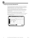
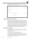
Data Transfer from Backup Unit to Active Unit
Eight bytes (4 registers) of data can be transferred from the backup unit to the active unit
during the input data transfer before the logic solution. To initiate this transfer, the
backup unit executes SVCREQ #27 (Write to Reverse Transfer Area) to copy eight bytes
of data from the reference specified by PARM to a temporary buffer (SVCREQ #27 on
the active unit will have no effect). This transferred data will be stored in a temporary
buffer on the active unit.
In the active unit, SVCREQ #28 (Read from Reverse Transfer Area) is then executed to
copy the eight bytes of data from the temporary buffer to the reference specified by
PARM (SVCREQ #28 will have no effect on the backup unit).
Note
There is always a one sweep delay between sending data to the active
unit using SVCREQ #27 and reading the data using SVCREQ #28 on
the active unit.
This data copied from the buffer is not valid
during the first scan after either unit has transitioned to RUN;
while the backup unit is in STOP mode;
if the remote unit does not issue a service request to the sending unit.
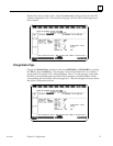
An example of this data transfer is described below.
This data should not be used if REM_RDY is off or if REM_RDY is transitioning to on.
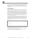
If the following two rungs are placed in the program logic of both units, the backup unit
will send %P0001 through %P0004 to the active unit. The active unit will read the data
into %P0005 through %P0008. %P0001 through %P0004 on the active unit and %P0005