


2
20 Series 90-70 Hot Standby CPU Redundancy User’s Guide – December 1993
GFK-0827
C
B
T
M
R
C
M
31
PRIMARY UNIT SECONDARY UNIT
30
P
S
P
S
B
T
M
R
C
M
Redundancy Communications Link
Redundancy Communications Link
G
B
C
G
B
C
P
U
C
P
U
( RACK 0 )
( RACK 0 )
a47005
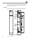
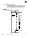
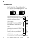
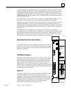
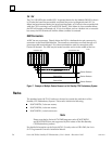
Figure 6. Example of RCM Location in a Hot Standby CPU Redundancy System
RCM System Status LEDS
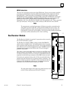
A Hot Standby CPU Redundancy system has two RCM modules, each with five LEDs
and a momentary pushbutton switch for manually switching between the active and the
backup units. The LEDs will always be updated by the appropriate system. The RCM
has two internal timers that will automatically turn off four of the LEDs (not the board
OK LED) if the LEDs have not been updated within a specified time period. The two
remote LEDs and the two local LEDs have separate timers since they are controlled from
different systems.
The RCM has five LEDS:
BOARD OK
LOCAL SYSTEM READY
LOCAL SYSTEM ACTIVE
REMOTE SYSTEM READY
REMOTE SYSTEM ACTIVE.
These LEDs report the status of the health of the RCM and the control status of the Hot
Standby CPU Redundancy system. The status provided by these LEDs is also provided
in an area of %S memory (%S33 - %S39) which is accessible from the user logic program
but cannot be altered or overridden. The LEDs have the following meanings and uses.
Note that the term Local Unit when associated with a particular RCM refers to that unit
in which the RCM resides. Remote Unit refers to that unit in which the RCM is
configured by the system for addressing as being in rack 7, slot 1. Each RCM will have
an associated local and remote unit.
BOARD OK
This LED will come on when the diagnostics are complete and the RCM has been
determined to be operating normally. It will remain on unless the RCM fails.
LOCAL SYSTEM READY
Indicates whether the local unit is ready to become the active unit in a redundant PLC
configuration. If the LED is on, the local unit has been configured for redundancy, is in
RUN mode, and has performed sufficient initialization, diagnostics, and hand–shaking
to take control of the redundant system if selected as the active unit. It is the
responsibility of the local unit to set the state of this LED at least once during each
sweep; if the local unit is unable to set (or fails to set) the state of the LED, the hardware
will force the LED to off after the timer has timed out.