


1
6 Series 90-70 Hot Standby CPU Redundancy User’s Guide – December 1993
GFK-0827
for three consecutive Genius I/O bus scans, the outputs are then controlled by the
Genius Bus Controller at serial bus address 30 (Genius Bus Controller in the Secondary
PLC).
If output data is not available from either bus address 31 or 30, the outputs go to their
configured default (OFF or hold last state). The PLC at serial bus address 31 always has
priority, therefore when the PLC with serial bus address 31 is On-line, it always has
control of the outputs.
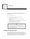
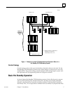
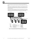
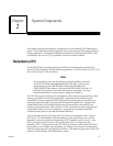
The redundancy system configuration is shown in the following figure. This example
configuration shows only the redundancy system components. As described previously,
a system can also contain Local I/O which is not a part of the redundancy scheme.
C
P
U
C
P
U
B
T
M
R
C
M
G
B
C
31
PRIMARY UNIT SECONDARY UNIT
30
B
L
O
C
K
B
L
O
C
K
S
C
A
N
N
E
R
REMOTE DROP
I
O
I
O
I
O
I
O
I
O
I
O
P
S
I
O
I
O
P
S
P
S
B
T
M
R
C
M
G
B
C
B
L
O
C
K
other Genius devices
*
TERMINATED I/O CABLE
*
TERMINATED I/O CABLE
a47001
Legend
PS.................... Power Supply.............................................. IC697PWRXXX
CPU................. Central Processor Unit.............................. IC697CPU780
BTM................. Bus Transmitter Module............................. IC697BEM713
RCM................ Redundancy Communications Module..... IC697RCM711
GBC................ Genius Bus Controller................................ IC697BEM731
BLOCK........... Genius I/O Block........................................ IC660XXXYYY
SCANNER....... Remote I/O Scanner.................................... IC697BEM733
*...................... Terminated I/O Cable................................. IC697CBL811/826
Figure 2. Synchronized Hot Standby CPU Redundancy System Configuration