


2
26 Series 90-70 Hot Standby CPU Redundancy User’s Guide – December 1993
GFK-0827
CH 1 OK
The CH 1 OK LED is the middle LED. It operates identical to the Module OK LED in that it
is ON after the board has successfully completed the power-up diagnostics and OFF if a
failure has been detected during the power-up diagnostics, or if its bus or bus controller fails
while the CPU is running (even in the STOP mode). If the failure is a bus controller failure,
the LED will remain permanently off. If it is a bus failure, such as a broken wire or excessive
bus errors, the LED remains off until the failure condition is corrected.
GBC Connectors
A GBC has two connectors. Directly below the LED is a dedicated nine-pin connector for
connection to the Hand-Held Monitor. The actual bus connections are made through a 12
point removable terminal board. Six of these terminals are used for connection to the
Genius I/O channel. The GBC may be located on either end or in the middle of the bus.
C
P
U
C
P
U
B
T
M
R
C
M
G
B
C
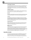
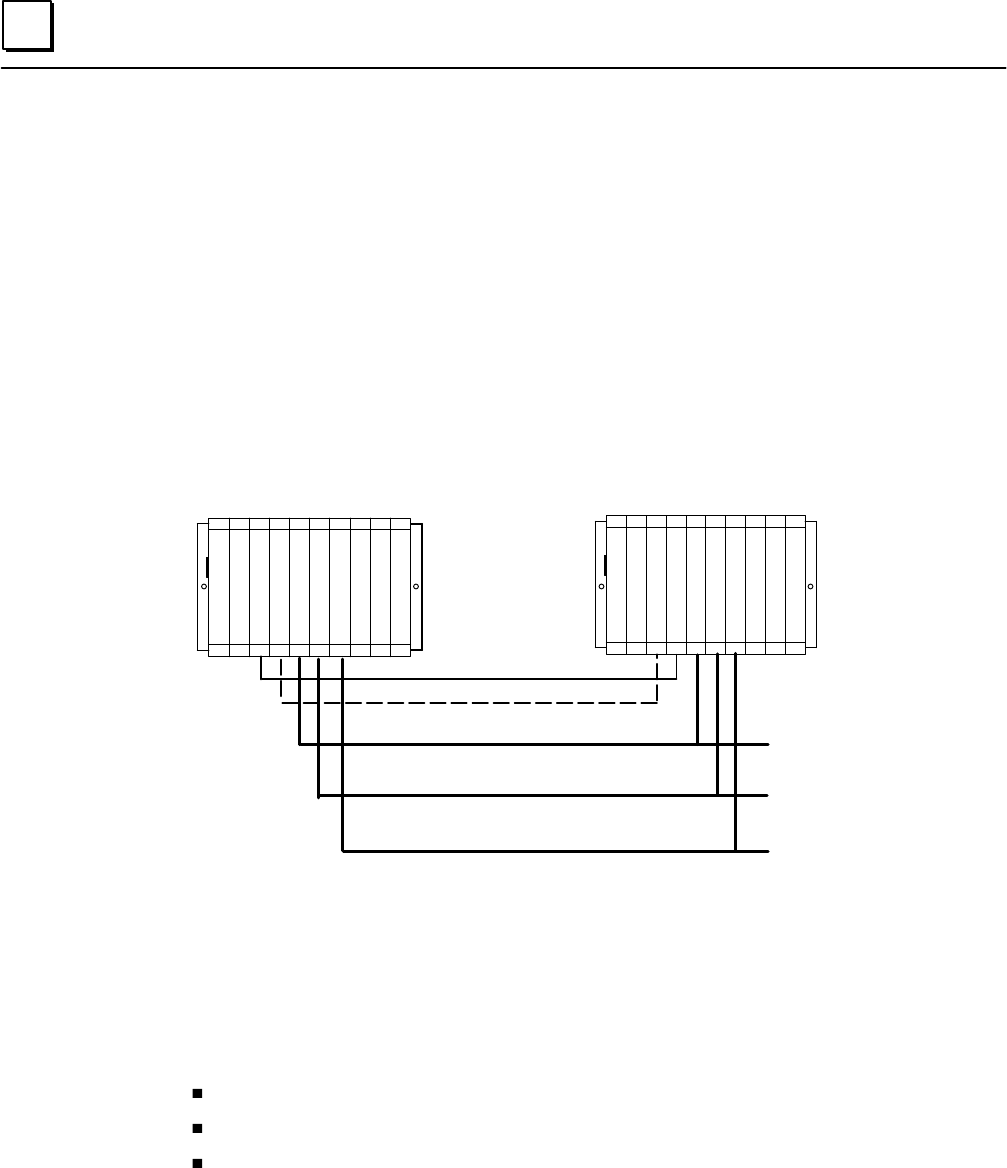
PRIMARY UNIT SECONDARY UNIT
30
P
S
P
S
B
T
M
R
C
M
G
B
C
31
G
B
C
31
G
B
C
G
B
C
30
G
B
C
30
31
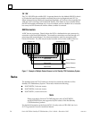
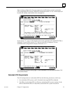
Genius Bus
Genius Devices
Genius Devices
Genius Devices
Genius Bus
Genius Bus
a47007
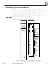
Figure 7. Example of Multiple Genius Busses in a Hot Standby CPU Redundancy System
Racks
The standard series 90-70 I/O racks may be used to contain the modules in a Hot
Standby CPU Redundancy System.. These racks include the following:
IC697CHS750, 5-slot rear mount;
IC697CHS790, 9-slot rear mount;
IC697CHS791, 9-slot front mount.
Note
Please note that he Series 90-70 VME Integrator racks (IC697CHS782
and IC697CHS783) are not supported by this release of the Hot Standby
CPU Redundancy product.
For detailed information on the Series 90-70 I/O racks, refer to GFK–0262, the Series
90-70 Programmable Controller Installation Manual.