Section 9 Bus State Controller
R01UH0134EJ0400 Rev. 4.00 Page 273 of 2108
Sep 24, 2014
SH7262 Group, SH7264 Group
Bit Bit Name
Initial
Value R/W Description
1, 0 WTRC[1:0]* 00 R/W Number of Idle Cycles from REF Command/Self-
Refresh Release to ACTV/REF/MRS Command
Specify the number of minimum idle cycles in the
periods shown below.
From the issuance of the REF command until the
issuance of the ACTV/REF/MRS command
From releasing self-refresh until the issuance of
the ACTV/REF/MRS command.
The setting for areas 2 and 3 is common.
00: 2 cycles
01: 3 cycles
10: 5 cycles
11: 8 cycles
Note: * If both areas 2 and 3 are specified as SDRAM, WTRP[1:0], WTRCD[1:0], TRWL[1:0],
and WTRC[1:0] bit settings are used in both areas in common.
If only one area is connected to the SDRAM, specify area 3. In this case, specify area 2
as normal space or SRAM with byte selection.
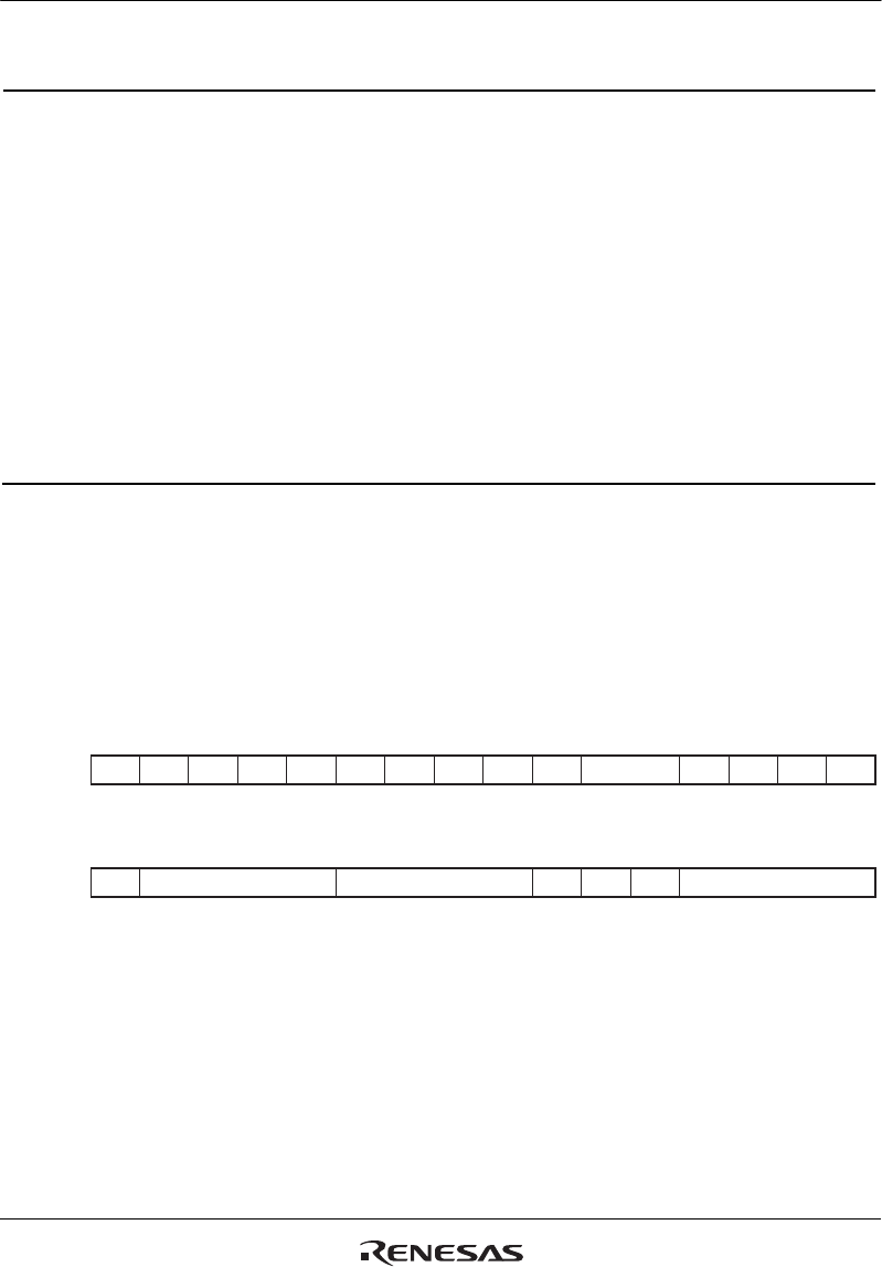
(4) PCMCIA
CS5WCR, CS6WCR
31 30 29 28 27 26 25 24 23 22 21 20 19 18 17 16
15 14 13 12 11 10 9 8 7 6 5 4 3 2 1
0
0000000000000000
RRRRRRRRRRR/WR/WRRRR
0000010100000000
R R/W R/W R/W R/W R/W R/W R/W R/W R R R R/W R/W R/W R/W
Bit:
Initial value:
R/W:
Bit:
Initial value:
R/W:
---------- SA[1:0] - - - -
- TED[3:0] PCW[3:0] TEH[3:0]WM - -


